 |
|||
|
|
|||
|
|
|||
| ||||||||||
|
|
 TM 9-2910-226-34
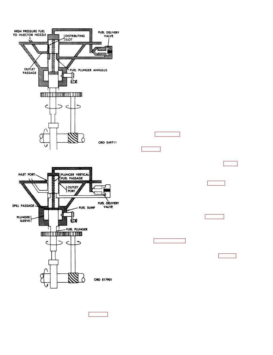
ports). As the spill passage in the fuel plunger
breaks over the top edge of the plunger sleeve,
pumping pressure is relieved and fuel delivery
terminates despite continued upward movement of
the fuel plunger.
b. When the plunger sleeve is raised, the spill
passage remains covered by the plunger sleeve until
relatively late in the plunger stroke. Hence, the
effective stroke of the fuel plunger is longer and more
fuel is delivered. When the plunger sleeve is lowered
the spill pas sage is uncovered by the plunger sleeve
relatively sooner in the plunger stroke. Hence, the
effective stroke of the fuel plunger is shorter and less
fuel is delivered.
c. When the plunger sleeve is lowered to its ex-
treme point, the spill passage is uncovered by the
top edge of the plunger sleeve before the upper end of
the fuel plunger can cover the fuel ports. Under this
condition, no pressure can be built up and no fuel can
be delivered. This is the fuel shutoff position.
1-25. Speed Governing (Typical).
NOTE
The key letters shown below in parentheses
refer to figure 1-19 except where otherwise
indicated.
a. The camshaft has two forged governor weights
(UU, fig. 1-16) attached to it through pins in a
spider. As camshaft speed increases, the weights
move out ward away from the camshaft. Fingers on
Figure 1-26. Fuel delivery flow diagram.
the weights act against the sliding sleeve (VV, fig. 1-
16).
b. The sliding sleeve is compressed against the
fingers of the governor weights by the governor
inner and outer springs (RR and SS, fig. 1-16). The
tensions of these springs balance the action of the
governor weights at any given speed within the
normal range after the sliding sleeve has shifted.
Therefore, at any given engine speed, there is a
definite corresponding sliding sleeve position.
c. The sliding sleeve is connected to the fulcrum
lever (B) through pivot pins (G, fig. 1-19). The
fulcrum lever slides in grooves in the sliding sleeve
and as the sliding sleeve moves, the fulcrum lever
moves. The fulcrum lever is also connected through
linkages to the plunger sleeve in the hydraulic head. -
As noted in paragraph 1-23 above, the position of the
plunger sleeve determines the quantity of fuel
delivered.
at its lower end on a yoke (an integral part of the
fulcrum lever) which is connected to the operating
shaft (E). The operating lever (F), which connects to
the operating shaft, is actuated through linkage
from the vehicle driver's compartment. The position
of the operating lever determines fuel delivery and
engine speed.
e. With the operating lever in a stationary
of fuel delivery flow diagram.
Figure 1-27. End
position, the lower pivot of the fulcrum lever
1-24. Fuel Metering and Control. a. The quantity of
becomes fixed. If the engine load is increased, the
engine speed will momentarily decrease and the
fuel delivered per stroke is governed by variation in
the position of the plunger sleeve (fig. 1-27) with
governor weights will lack the centrifugal force
relation to the fixed port closing position (the point
necessary to balance the spring forces on the sliding
sleeve. The fulcrum lever then shifts and moves the
at which the top of the fuel plunger covers the fuel
1-28
|
|
Privacy Statement - Press Release - Copyright Information. - Contact Us |
