 |
|||
|
|
|||
|
Page Title:
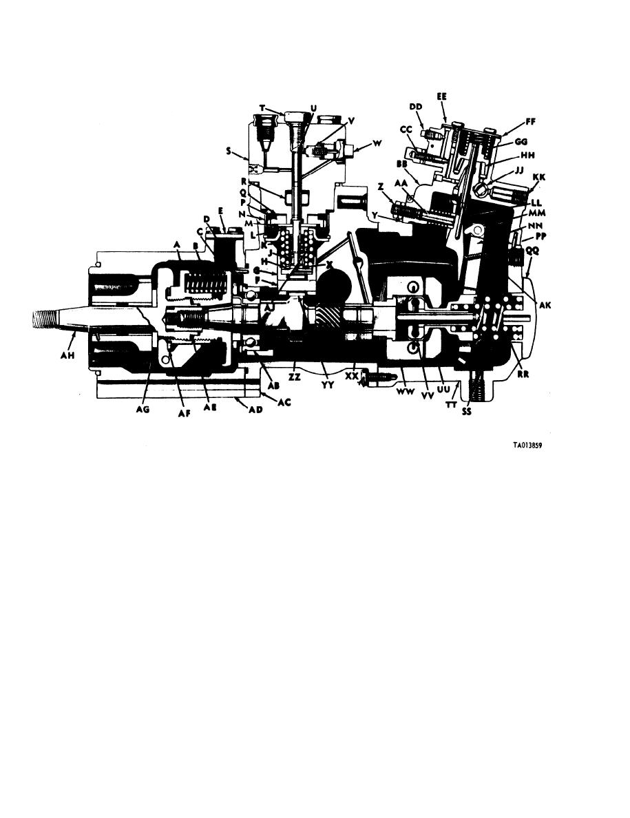
Figure 1-16. Metering and distributing fuel injection pump assembly (code B, C, D and E), left sectional view. |
|
||
| ||||||||||
|
|
 TM 9-2910-226-34
Sliding gear
W
Delivery valve screw
A
Governor inner spring
RR
Timing device spring
B
Plunger button
X
Governor outer spring
SS
Timing device hub
Density compensator gasket
C
Y
Governor housing
TT
Timing pointer
Z
D
Guide nut
Governor weight
UU
Timing cover
E
AA
Guide
VV
Sliding sleeve
F
Tappet roller pin
BB
Density compensator housing
Friction drive spider
WW
G
Tappet guide
Servo pressure valve
CC
Camshaft bushing type bearing
XX
Spring lower seat
H
Servo pressure tap
DD
YY
Tappet roller
Plunger lock
J
Compensator housing cover
EE
ZZ
Camshaft
K
Plunger inner spring
Housing cover gasket
FF
Camshaft ball bearing
AB
L
Spring upper seat
Servo spring
GG
Injection pump housing
AC
M
Plunger guide
HH
Spring piston
Timing device housing
AD
Drive gear retainer
N
Pressure regulating valve
JJ
End play spacer
AE
P
Plunger drive gear
KK
Fuel inlet port
AF
Sliding gear spacer
Gear thrust washer
LL
Piston link
AC
Spider thrust plate
G
Plunger sleeve
R
MM
Smoke limit cam
Weight and spider assembly
AH
S
Hydraulic head
NN
Governor fulcrum lever
Plunger outer spring
AJ
T
Plunger bore screw
PP
Stop plate
AK
Droop screw (use only on code B and E pumps),
U
Fuel plunger
Governor end cap
QQ
V
Fuel delivery valve
Figure 1-16. Metering and distributing fuel injection pump assembly (code B, C, D and E), left sectional view.
1-18
|
|
Privacy Statement - Press Release - Copyright Information. - Contact Us |
