 |
|||
|
|
|||
|
|
|||
| ||||||||||
|
|
 TM 9-2815-224-34&P
Turbrocharger Maintenance Instructions (Cont)
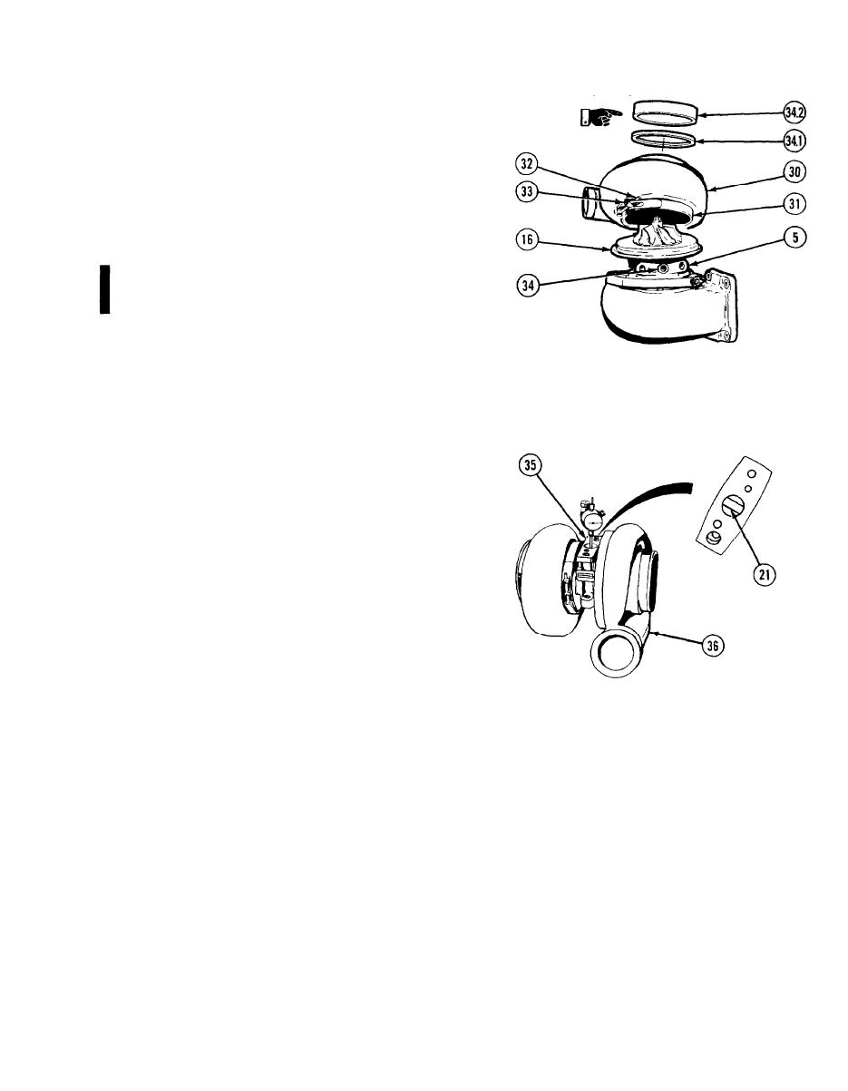
Aline matchmarks on compressor
(32)
housing (30) and center housing (5).
coupling (31) on backplate (16).
(34) Apply lubricating oil to threads of screw (32).
(35) Tighten locknut (33) to 110 to 130 lb-in. (12
to 15 Nm).
(36) Coat threads of brass fitting (34) with pipe
thread sealing compound and install. Tighten
to 240 lb-in. (27.1 Nm).
(36.1) Install seal (34.1) and turbocharger
guard (34.2) on intake side of compressor
housing (30).
(37) Position magnetic base, equipped with swivel
adapter, dial indicator, and extension rod, on
flat surface of housing inlet flange (35).
NOTE
Do not allow extension rod to touch sides of
center housing. Inaccurate readings can result
in poor fit and damage.
Insert extension rod into oil drain hole so
(38)
that rod is against turbine wheel shaft (21).
Move turbine wheel shaft (21) up and down.
(39)
Turbine wheel shaft must not move more
than 0.0070 in. (0.177 mm) or less than
0.003 in. (0.076 mm).
Disassemble and inspect turbocharger (36) if
(40)
fit of turbine wheel shaft (21) is not within
limits.
d. Follow-on Maintenance. None.
END OF TASK
14-55/(14-56 blank)
Change 2
|
|
Privacy Statement - Press Release - Copyright Information. - Contact Us |
