 |
|||
|
|
|||
|
Page Title:
Figure 3-93. Throttle stop screw adjust. |
|
||
| ||||||||||
|
|
 *TM 9-2815-213-34
setting.
(6) Set Idle Speed.
(a) Set throttle shaft to idle position.
(b) Set 4-way valve to "IDLE" position.
(c) Set speed to 600 rpm.
NOTE
Reading on pressure gage should be 22
p.s.i. If pressure is low, adjust idle
adjusting screw using idle adjusting tool
(32, fig. B-28) as shown in figure 3-94.
(Remove pipe plug to insert tool). To
lower pressure, back-out screw. If
pressure is low, and screw bottoms on
guide, washers will have to be added to
the spring end of the screw.
(d
Each time pipe plug is removed to
adjust idle screw, run pump until purged of air.
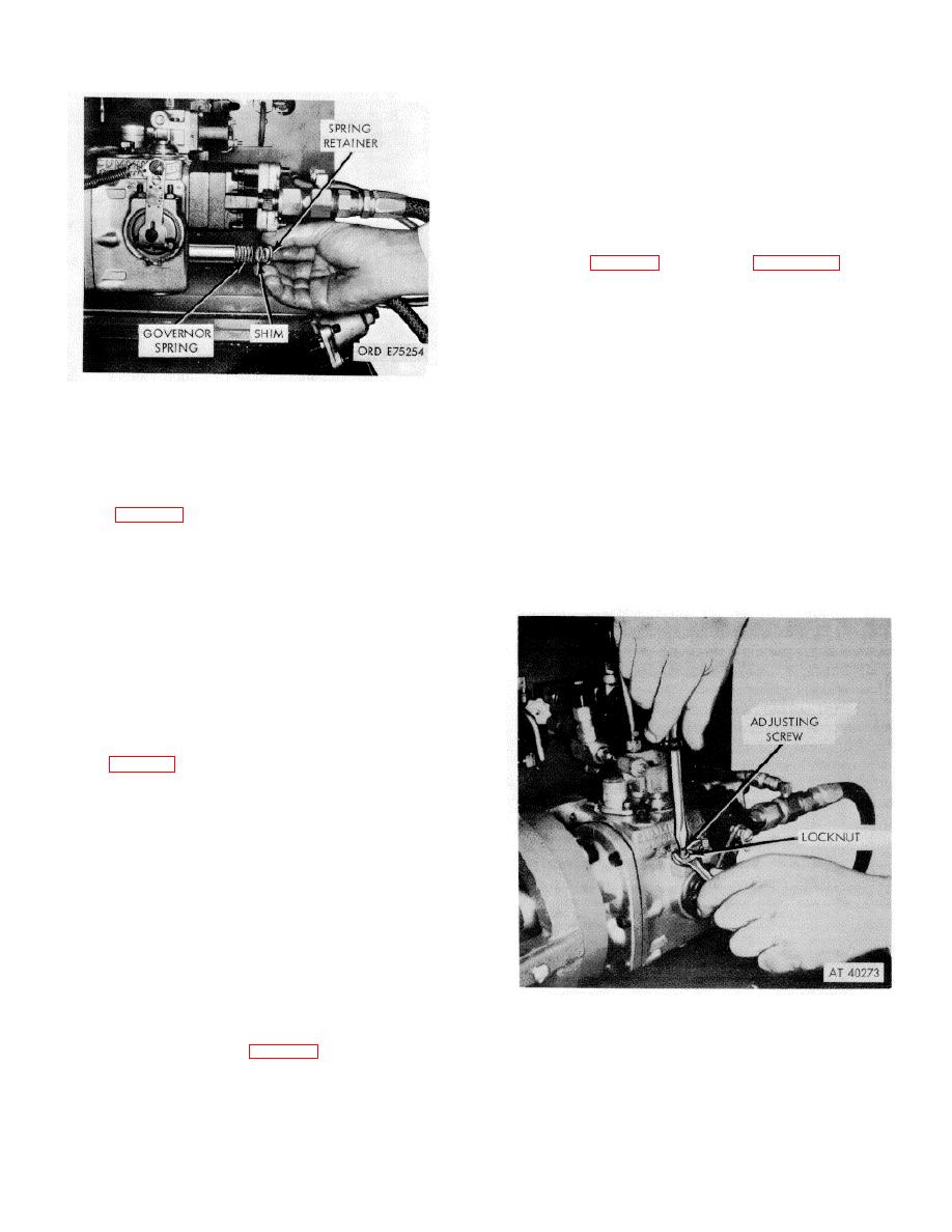
Figure 3-92. Governor spring shimming.
(7) Check Point Flow Tests.
(a) Set 4-way valve to "ROTAMETER"
p.p.h. with throttle fully open (3000 RPM).
position.
(b) Reduce speed to 500 rpm.
(b) Set throttle to full open position.
(c
Set 4-way valve to "LEAKA TEST"
(c) Operate pump at 2500 rpm and adjust
position.
flow to 445 p.p.h. Pressure gage should read 165-173
(d) Turn count selector switch to 1000 pulse
p.s.i.
position (fig. 3-80).
(d) Reduce speed to 2000 rpm and adjust
NOTE
flow to 335 p.p.h. Pressure gage should read 117-125
Fuel delivery should be 35cc-plus or
p.s.i.
minus 5-cc for a one minute period. The
(e) Reduce speed to 800 rpm and adjust
test stand has a maximum count of 1000
strokes, therefore, at 3000 RPM each
cycle will be of one-third minute duration,
and the fuel delivery will also be one-
third the above cc valves. (e) Pull out
fuel dumping lever ( 3-80).
(f) Remove throttle spring and manually
operate throttle.
(g) Depress pulse counter button to No. 1
burette (fig. 3-80) and push in fuel dumping lever.
NOTE
Burette will overflow before cycle is
completed, therefore, it is important to
push-in fuel dumping lever and return
throttle to idle position when burette is
filled.
(h) Increase speed to 3000 rpm and h
(i) Pull out fuel dumping lever and press
counter button to start count.
NOTE
At completion of count cycle the fuel de-
Figure 3-93. Throttle stop screw adjust.
livery in No. 1 burette should be 10 to
13.5 cc. If not to specification adjust
throttle stop screw (fig. 3-93) until fuel
delivery is to specification and lock
3-50
|
|
Privacy Statement - Press Release - Copyright Information. - Contact Us |
