 |
|||
|
|
|||
|
Page Title:
Figure 3-50. Injector cup-removal/installation. |
|
||
| ||||||||||
|
|
 *TM 9-2815-213-34
sulphur content in fuel or overload operating conditions.
(3) Enlarged or distorted spray holes, caused by
cleaning with drills, wires, or other instruments.
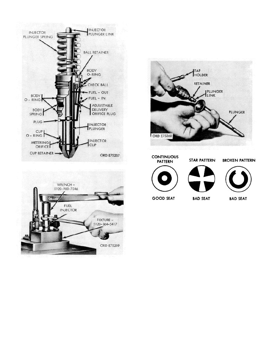
(4) Plunger seat pattern covers less than 40 %
continuous area around cup, cone or plunger bore (fig. 3-
52).
Figure 3-51. Injector Link-removal/installation.
Figure 3-49. Fuel injector PT (type C)
Figure 3-52. Plunger seat pattern.
b. Injector Body.
(1) Inspect injector body plunger bore for
scoring, if scores are too deep, injector body
should be replaced.
(2) Use strong magnifying glass to check
for burs, carbon, and distorted radii in orifices.
When injector orifices are damaged, the injector
will not function properly.
c. Injector Plunger.
Figure 3-50. Injector cup-removal/installation.
(1) Check closely for metal seizure caused
CAUTION
by scuffing or scoring.
Never alter size of injector spray holes.
(2) Spots or surface disruption at top of
plunger or at mid-point, usually are normal re-
a. Injector Cup. Inspect injector cup spray
sults of rocker lever thrust action. Unless metal is
holes and tip with magnifying glass and compare
displaced or wear is measureable at these points,
with new cup. Discard cup if any of following
conditions exist:
(1) Interior/or exterior abrasive wear.
(2) Corrosion damage and effect of exces-
sive heat, usually resulting from high acid or
3-24
|
|
Privacy Statement - Press Release - Copyright Information. - Contact Us |
