 |
|||
|
|
|||
|
Page Title:
Section XIV. Repair of Fuel Injectors |
|
||
| ||||||||||
|
|
 word "TOP" on gasket is visible. Be careful not to
*TM 9-2815-213-34
dislodge grommets as gasket is lowered over
rust preventive lubricant and install.
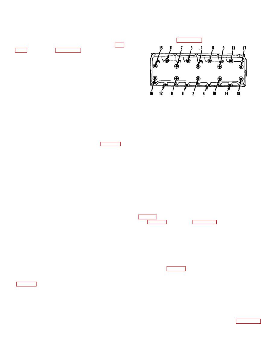
Tighten each in
grommet retainers.
sequence shown in figure 3-48.
f. Using cylinder head lifting plate (45, fig.
with suitable hoist and lower into place over
dowels.
g. Blow all liquid and dirt from cylinder head
capscrew holes with compressed air.
CAUTION
Keep rust preventative oil from internal
engine parts to prevent corrosive dam-
age.
h. Coat short cylinder head capscrews with
Section XIV. Repair of Fuel Injectors
3-71. General
NOTE
This section covers the disassembly, inspection,
repair, assembly and testing of injectors (fig. 3-49).
The injector is a simple mechanical unit which
Injector bodies and plungers are class fits, do not
receives fuel from the fuel pump, under pressure,
interchange.
and injects it through fine injector cup spray holes
b. Remove and discard O-Rings
into the combustion chamber. The description "PT
from injector
Injectors" is only used to in the cate that the injector
body.
is used with the PT fuel systems. The PT injectors
c. Disassemble clamp securing screen to injector
are mounted in the cylinder head and are cylindrical
body.
in shape. 'The V8-300 engine uses of PT type C
injector. It consists of two major assemblies: injector
NOTE
body and plunger; and the injector cup. The orifice
descriptions below are given for functional main-
Do not remove adjustable orifice plug from inlet
tenance purposes.
groove.
a. Adjustable Orifice Plug. The orifice plug
d. Place injector in injector cup wrench (30,
used in the inlet drilling of the cylindrical injec- tor
adjusts delivery of fuel. Fuel delivery is ad- justed by
(29, fig. B-28) as shown in figure 3-50.
changing the orifice plug or by burnish- ing the plug in
e. Remove injector cup; note size markings on
operating position. Some ori plugs have a flange and
injector body for future reference.
require a gasket bene the flange.
f. Remove ball retainer, ball, and gasket from
b. Drain Orifice. The drilled orifice in cup E
top of injector body, discard gasket.
of the injector is the drain drilling. This orifice is fixed
g. Place injector plunger in suitable holding
in size and must not be altered in any way.
device with spring retainer upward.
c. Metering Orifice. The orifice in cup end
h. Pull link and retainer as an assembly.
of the injector allows fuel to enter plunger bore and
i. Using a collet type hand tap holder, pull
cup; do not alter in any manner.
injector links (fig. 3-51).
3-72. Disassembly
3-73. Cleaning
Clean injector components in accordance with paragraph 2-
a. Lift out injector plunger and spring. Tag
5.
mating parts.
3-74. Inspection
Perform general inspection of components in accordance
with wear limits in repair and rebuild standards (para. 3-183).
Detailed inspection of injector components follow.
3-23
|
|
Privacy Statement - Press Release - Copyright Information. - Contact Us |
