 |
|||
|
|
|||
|
Page Title:
Section IV. Repair of Connecting Rod and Piston Assembly |
|
||
| ||||||||||
|
|
 *TM 9-2815-213-34
tighten cap bolts. Recheck end clearance. If the original
shaft and thrust rings are installed and end clearance
exceeds the wear limits the thrust rings must be
replaced.
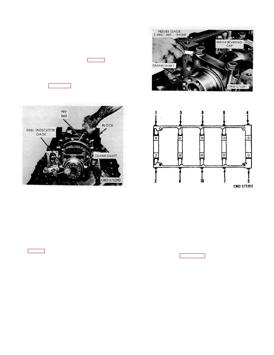
l. Check clearance between main bearing caps
and block at side bolt contact area on each of cap;
clearance must be 0.002-0.005-inch fig. 3-7).
m. Coat threads of bearing cap side bolts v
OE-10 lubricant.
n install bolts and flat washers engage threads by
hand.
o. Refer to figure 3-8 for bolt tightening sequence.
Torque each bolt to 70-75 foot-pounds 35-40 foot-
pounds increments.
Figure 3-7. Bearing cap to block clearance check.
Figure 3-6. Crankshaft end clearance check.
Figure 3-8. Side bolt tightening sequence.
Section IV. Repair of Connecting Rod and Piston Assembly
; depressions with a 1/16-inch radius or less are not
3-13. Disassembly
acceptable on the edge of the I beam section or on the
a. Remove piston pin snap rings.
periphery of the forging. Nicks, notches, or gashes
b. Heat pistons in hot water for several minutes to
1/32-inch or less in depth may be removed by grinding
facilitate pin removal. Push pin from piston with thumb
and blending to the original contour within a minimum
pressure.
distance of inch on either side of the defect.
c. Using a suitable ring expander remove piston
b. Assemble cap to rod and tighten down bolt nuts
rings (fig. 3-9).
to proper torque (para. 3-186).
c. Check crankpin bore with inside micrometers.
NOTE
The bore must be within limits shown in paragraph 3-
177. Out-of-round limits should not exceed 0.00075
Maintain each rod and piston assembly
inch.
as a group. Do not mix with other
d. Using a dial bore gage, check crankpin bore for
assemblies.
out-of-round condition. Out-of-round limits must not
exceed 0.00075 inch.
3-14. Cleaning
e. Using inside micrometers, check piston pin
Refer to paragraph 25 for cleaning instructions.
bushing diameter. Piston pin bushing bore must
3-15. Inspection
a. Inspect rod visually for nicks, notches gashes
3-5
|
|
Privacy Statement - Press Release - Copyright Information. - Contact Us |
