 |
|||
|
|
|||
|
Page Title:
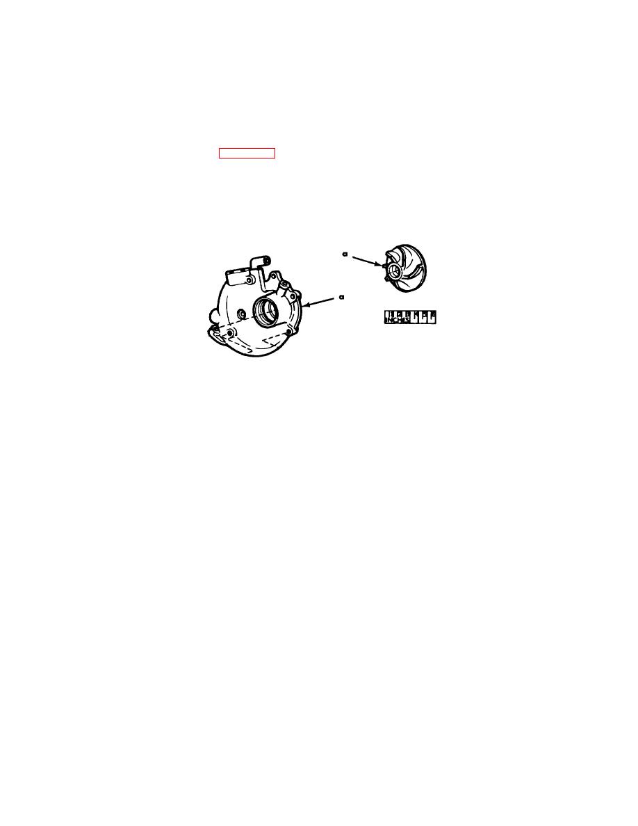
Figure 3-113. Water pump-points of measurement. |
|
||
| ||||||||||
|
|
 *TM 9-2815-213-34
Fig.
Ref.
Point of Measurement
New Dimensions
Wear Limits
No.
Letter
(inches)
(inches)
c
Injector sleeve-upper inside diameter .........................................
1.140 to 1.150
*
3-110.
c
Guide-outside diameter ..............................................................
0.4332 to 0.4335
0.4322
y
Protrusion above the head..........................................................
2.0900 to 2.1100
*
c
Inside diameter ...........................................................................
0.4340 to 0.4360
0.4400
e. Injector Plunger Spring Data (para. 3-74).
3-110.
z
Free length..................................................................................
2.4500 to 2.4900
*
Load at:
2.139 inches................................................................................
87.6 to 95.6 lbs.
*
1.975 inches................................................................................
13 to 147 Ibs.
*
z
Injector cup torque-ft. Ibs. ..........................................................
50 to 55
z
Orifice plug torque-ft. Ibs. ..........................................................
6to 8
Figure 3-113. Water pump-points of measurement.
3-113.
a
Impeller to body clearance..........................................................
0.0100 to 1.0200
*
3-185. Assembly Data
3-114.
a
Front cover
Crankshaft to seal bore ........................................................
0.0050
3-114.
b
Flywheel and Housing
Housing bore run-out............................................................
0.010
*
b
Housing face run-out ..................................................................
0.008
*
3-114.
Flywheel pilot bearing .................................................................
*
c
Bore run-out ................................................................................
004
*
c
Clutch face run-out .....................................................................
005
*
3-186. Torque Specifications
CAUTION
Bolts threaded into aluminum may require
reduction in torque of 30 percent or more,
unless inserts are used.
Fig.
Item
Nut or bolt size
Lb-ft. torque
. Cylinder Block Group.
2-29
*Main bearing stude nuts or cap screws ................................
3/4x 5.8in.
170 to 180 +
3-8
Main bearing side bolts ..........................................................
5/8x31/4in.
70 to 75
2-28
*Connecting rod nuts..............................................................
9/16x4.4in.
60 to 65+
2-6
Vibration damper mounting cap screws .................................
5/5x3y4 in.
190 to 200
Crankshaft pipe plugs ............................................................
1/8 in.
5
Engine block-pipe plugs .........................................................
1/8 in.
5 to 10
Engine block-pipe plugs .........................................................
in.
45to 55
3-71
|
|
Privacy Statement - Press Release - Copyright Information. - Contact Us |
