 |
|||
|
|
|||
|
|
|||
| ||||||||||
|
|
 *TM 9-2815-213-34
e. Block Mating Surfaces. Check top machined
(2) Check ID of the sleeve against limits
specified in repair and rebuild standards (para 3-179).
surfaces of block with straight edge and feeler gage. If
Measurements shall be made at middle, and skirt of
warped, distorted or uneven replace block.
f. Expansion Plugs. Inspect all expansion plugs
sleeve. Replace any s worn beyond specified limits.
for evidence of coolant leakage. Replace all plugs that
are defective.
NOTE
g. Miscellaneous Parts. Inspect main bearing cap
Refer to paragraph 3-2.c. for sleeve
screws, washers, and all pipe plugs. Check for
removal. If any sleeve requires removal
damaged threads, nicks, burs, and other unserviceable
perform steps 3 and 4 below.
conditions. Replace all unserviceable parts.
3-5. Repair
(3)
Discard preformed packings and crevice
Repair of the cylinder block is limited to general
seals.
procedures as outlined in paragraph 2-7. Any defect, or
(4) Using block gage (24, fig. B28) cylinder
measurement outside the tolerances listed in paragraph
counterbore and bore against limits specified in repair
and rebuild standards (13-175).
Replace block if
measurements are beyond specified limits.
36. Assembly
a. Camshaft Bushings. Refer to paragraph 3
(1) Install and tighten bearing caps. Refer to
2.b., and reverse the order of removal.
b. Pipe Plugs. Install all pipe plugs. Refer to
(2) Check
bearing
bores
horizontally,
vertically, and diagonally against limits specific repair
sealing tape or lead solder to prevent leakage.
and rebuild standards (para. 3-175).
c. Cylinder Sleeves.
(3) Check alignment of bore using bearing bore
alignment checking bar (19, fig. B-28)
NOTE
NOTE
Before installing sleeves insure that
Inspect bar for run-out and OD prior to
each sleeve protrusion is 0.004 to 0.006-
use. Bar must be 3.7510-3.7506-inch
inch.
OD and straight within 0.0005 in full
length. Bar must pass through all bores
(1) Install crevice seal ring on machined
and turn freely. Replace any cap that
surface above packing ring grooves, as shown in figure
prevents free passage and turning.
(2) Lubricate packing rings with light coating of
d. Tappet Bores. Check valve and injector pet
OE-10 lubricant.
bores against limits specified in repair rebuild standards
(3) Roll each ring into grooves (fig. 3-4) and
straighten using ring mold mark as a guide.
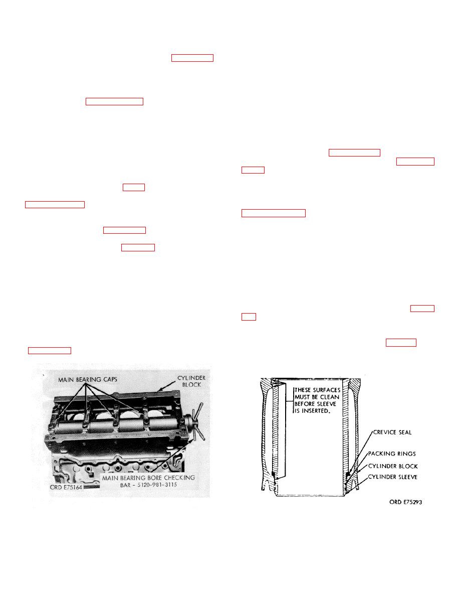
Figure 3-3. Main bearing bore alignment check
Figure 3-4. Cylinder sleeve sells installation
3-2
|
|
Privacy Statement - Press Release - Copyright Information. - Contact Us |
