 |
|||
|
|
|||
|
Page Title:
FIGURE 510. CONNECTING CYLINDER NO. 4, 5, AND 6 FUEL INJECTION TUBES (EARLY MODEL ENGINES). |
|
||
| ||||||||||
|
|
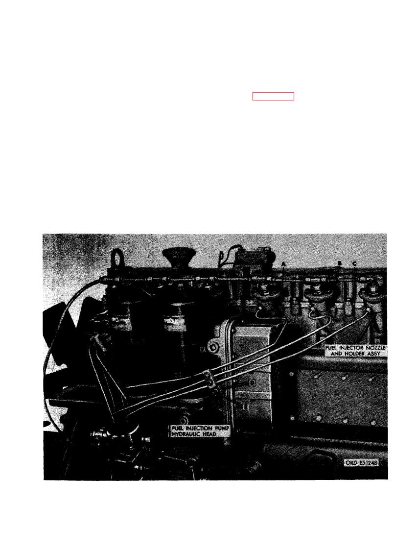 (2) Figure 509. (A) Connect fuel injection
inch plain washers, and 1/4- inch self-
tube to nozzle and holder in cylinder
locking nuts to secure fuel injection tube
No. 4. Remove dust cover from No. 4
clamps together. (H) Move fuel injection
port opening in pump hydraulic head
tube dust caps down over tube nuts and
and connect tube to head. (B) Connect
fuel injection pump ports.
fuel injection tube to nozzle and holder
in cylinder No. 5. Remove dust cover
(3) Figure 510. (A) Connect fuel injection
from No. 5 port opening in pump hy-
tube to nozzle and holder in cylinder
draulic head and connect tube to head.
No. 4. Remove dust cover from No. 4
port opening in pump hydraulic head
(C) Connect fuel injection tube to noz-
zle and holder in cylinder No. 6. Remove
and connect tube. (B) Connect fuel in-
dust cover from No. 6 port opening in
jection tube to nozzle and holder in
pump hydraulic head and connect tube
cylinder No. 5. Remove dust cover
to head. (D) Install injection tube inner
from No. 5 port opening in pump hy-
clamp on oil cooler and oil filter hous-
draulic head and connect tube. (C) Con-
ing stud. Position clamp so tubes fit in
nect fuel injection tube to nozzle and
recesses. (E) Install 3/8-inch plain
holder in cylinder No. 6. Remove dust
washer, 3/8- inch lock washer, and 3/8-
cover from No. 6 port opening in pump
inch plain nut to secure inner clamp.
hydraulic head and connect tube. (D) In-
(F) Install fuel injection tube outer
stall injection tube inner clamp on oil
clamp over fuel injection tubes. (G) In-
cooler and oil filter housing stud. Posi-
stall two 1/4 x 1-3/8 cap screws, l/4-
tion clamp so tubes fit in recesses.
TUBES (EARLY MODEL ENGINES).
323
|
|
Privacy Statement - Press Release - Copyright Information. - Contact Us |
