 |
|||
|
|
|||
|
Page Title:
FIGURE 508. CONNECTING CYLINDER NO. 1, 2, AND 3 FUEL INJECTION TUBES. |
|
||
| ||||||||||
|
|
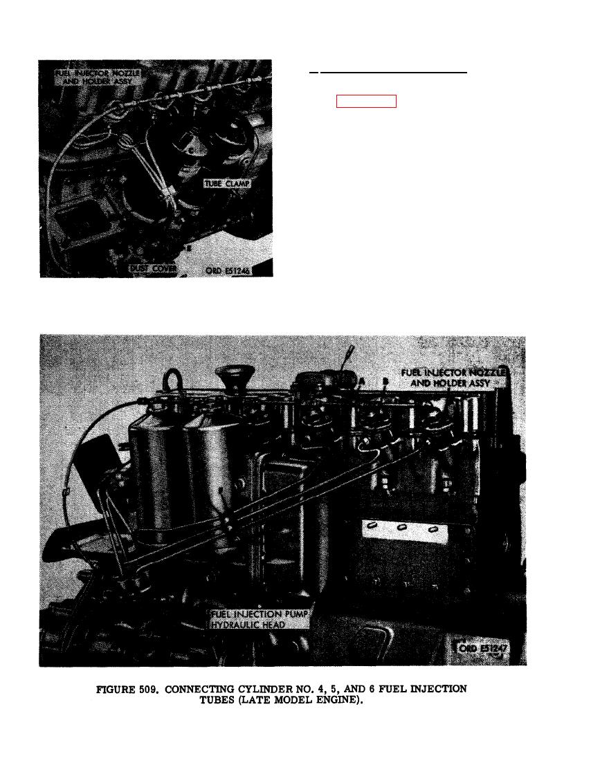 c. Install Fuel Injection Tubes. Install fuel
injection tubes as follows.
(1) Figure 508. (A) Connect fuel injection
tube to nozzle and holder in cylinder
No. 1. Remove dust cover from No. 1
port opening in pump hydraulic head
and connect tube. (B) Connect fuel in-
jection tube to nozzle and holder in
cylinder No. 2, Remove dust cover from
No. 2 port opening in pump hydraulic
head and connect tube. (C) Connect fuel
injection tube to nozzle and holder in
cylinder No. 3. Remove dust cover f rom
No. 3 port opening in pump hydraulic
head and connect tube. (D) Install two
fuel injection tube clamps and secure
with two 1/4 x 1-3/8 cap screws, 1/4-
inch plain washers, and 1/4- inch self-
locking nuts. (E) Slide dust caps over
tube nuts and injection pump ports.
1, 2, AND 3 FUEL INJECTION TUBES.
322
|
|
Privacy Statement - Press Release - Copyright Information. - Contact Us |
