 |
|||
|
|
|||
|
Page Title:
INSTALLATION OF OIL PUMP ASSEMBLY, OIL PUMP TUBES, AND OIL PAN |
|
||
| ||||||||||
|
|
 connecting rod being installed is at
(2) Figure 480. (A) Position piston ring
bottom center. The remaining piston
compressor- 10899159 over cylinder
and connecting rod assemblies can be
liner with small inside diameter end
installed in a sequence of No. 6, No. 2
toward liner. (B) Install connecting rod
and 5, and 3 and 4, to prevent unneces-
through compressor. Guide piston skirt
sary crankshaft rotation.
through compressor and gently tap the
piston with a wooden hammer handle
(2) Install remaining connecting rod caps
(or other suitable tool) until top piston
with assembled connecting rod sleeve
ring enters cylinder liner. Remove
bearings as directed in paragraph b
piston ring compressor -10899159. With
above.
the aid of an assistant to guide connect-
ing rod, continue to tap piston until
bearing seats on crankshaft journal.
BLY, OIL PUMP TUBES, AND OIL PAN
a. Install Oil Pump Assembly. Refer to fig-
ure-s 281 and 282 and reverse the sequence of
illustrations and instructions to install the oil
pump assembly.
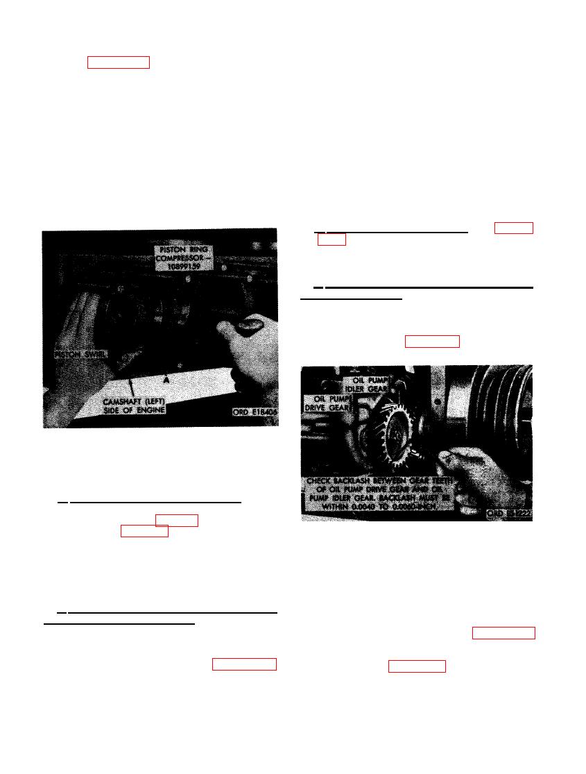
b. Check oil Pump Drive Gear and Oil Pump
Idler Gear Backlash.
(1) Check oil pump drive gear and oil
pump idler gear backlash following in-
structions on figure 481.
NECTING ROD ASSEMBLY USING PISTON
RING COMPRESSOR - 10899159.
b. Install No. 1 Connecting Rod Cap. Install
the-connecting rod cap and sleeve bearings on
No. 1 connecting rod (fig. 284). The location
number on cap (fig. 343) must correspond to
the number on connecting rod and numbers must
be toward the camshaft side of the engine.
GEAR AND OIL PUMP IDLER GEAR
Secure the cap to the rod by installing two con-
BACKLASH.
necting rod bolts. Tighten the connecting rod
bolts to a torque of 800 pound inches.
(2) When oil pump drive gear and oil pump
c. Install Remaining Piston and Connecting
idler gear backlash is not within spec-
Rod Assemblies and Rod Caps.
ifications, remove oil pump assembly
following instructions for figures 281
(1) Install remaining piston and connecting
and 282.
rod assemblies in the same manner
following instructions for figure 480.
(3) Refer to figure 304 and remove front
Rotate crankshaft so that connecting
main bearing cap with assembled oil
rod journal for respective piston and
pump idler gear.
306
|
|
Privacy Statement - Press Release - Copyright Information. - Contact Us |
