 |
|||
|
|
|||
|
|
|||
| ||||||||||
|
|
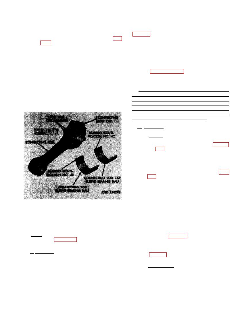 and cap for cylinder No. 4. Connecting
ring lands. Clean oil holes in oil rings and oil
rod sleeve bearings are also marked
ring grooves. Remove carbon from oil holes
to indicate their locations. The con-
necting rod sleeve bearing halves (fig.
23 drill (0.154-inch). Remove carbon from
cavity and swirl inlet in piston head. Clean
marked "4R" for the half that fits into
carbon from piston pins and bores with crocus
the rod, "4C" for the bearing that fits
cloth dipped in dry-cleaning solvent or mineral
into the cap. The identification marks
spirits paint thinner. Clean connecting rod
appear inside the alinement tang of
sleeve bearing halves with cloth dipped in dry-
each bearing half. If the connecting rod,
cleaning solvent or mineral spirits paint thinner.
cap, or bearing markings are oblit-
Refer to paragraph 152 for general cleaning
erated, mark with a grease pencil for
instructions for cleaning connecting rods and
installation in their original positions.
caps.
Install rod cap on connecting rod using
the two connecting rod bolts after con-
Caution: Use goggles, rubber gloves, and
necting rod sleeve bearing halves have
rubber apron when cleaning parts in carbon
been removed.
removing compound. Provide adequate ventila-
tion. Avoid inhalation of fumes and skin contact.
If compound is splashed on skin, flush with
water and wash with alcohol. Alcohol containing
2 to 3 percent camphor is preferred.
b. Inspection.
(1) Piston. Inspect piston for cracks, burned
piston ring lands, and damaged piston
skirt. Thoroughly inspect piston. Fig-
ure 344. (A) Inspect general conditon of
No. 1 and No. 2 compression ring
grooves in piston. Place a 0.1125-inch
diameter pin on each side of piston in
tapered ring groove as shown. Refer
to repair and rebuild standards (par.
tance between pins using a micrometer.
Measurement should be from 4.2920 for
used piston to 4.3040 for new piston.
Replace piston when measurement is
below 4.2920 or the tapered ring groove
is worn beyond limits specified. (B)
Check condition of the spherical com-
bustion chamber at top of each piston
BEARING AND CONNECTING ROD IDENT-
using a new piston for comparison.
IFICATION NUMBER LOCATIONS.
Chamber must not be burned or dis-
torted. (C) Check piston pin bore against
limits specified in repair and rebuild
Note. The key letters shown below in paren-
standards (par. 292). Replace piston and
theses refer to figure 322 except where other-
piston pin when piston pin bore is over-
wise indicated.
size. (D) Check piston against limits
specified in repair and rebuild standards
a. Cleaning. Clean piston (YY), rings (TT,
UU, and VV), piston pin (XX), and retaining
rings (WW) by soaking in carbon removing com-
pound (MIL-S-12382 (ORD) type 1). Do not des-
(2) Piston rings. Inspect compression rings
(TT and UU) and oil control rings
troy or remove connecting rod or bearing loca-
(VV) for scuffing, scoring, chipping,
tion markings. Scrape remaining carbon de-
posits from piston ring grooves with a scraper
scratches, or abrasions. Pay particular
attention to rings which were found to
or a broken piston ring. Do not scratch or gouge
|
|
Privacy Statement - Press Release - Copyright Information. - Contact Us |
