 |
|||
|
|
|||
|
|
|||
| ||||||||||
|
|
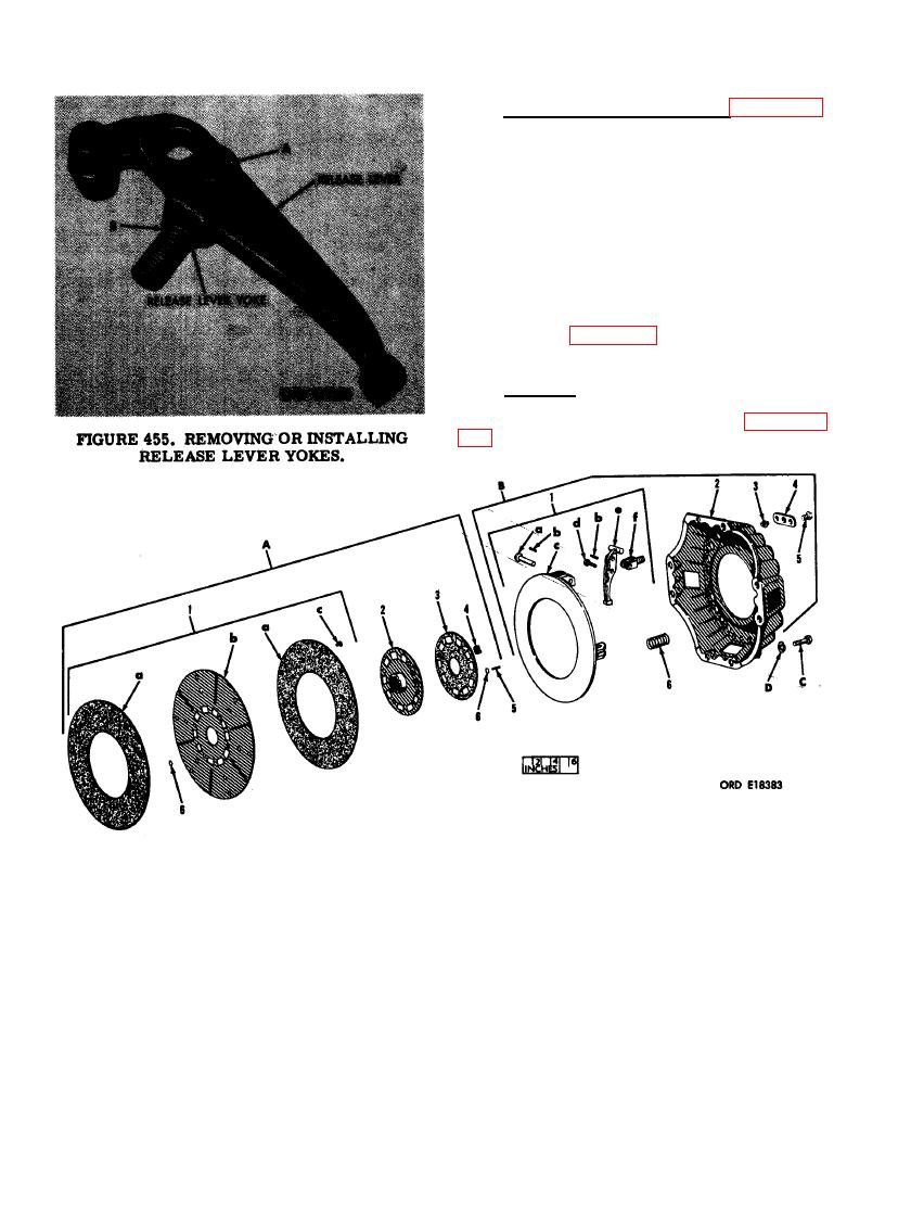 h. Remove Release Lever Yokes. Figure 455.
(A)-File off mushroomed end of pin opposite pin
head and drive out the yoke pin. (B) Remove re-
lease lever yoke from release lever. Remove
bearing reattaining pin and 19 needle rollers.
Note. Remove the three remaining release
lever yokes and bearing rollers in the same
manner.
Note. The key letters shown below in paren-
theses refer to figure 456 except where otherwise
indicated.
a. Cleaning. Thoroughly clean clutch cover
parts, except driven member assembly (A) and
clutch facings (A-1-a) as directed in paragraph
a - Release lever pin
A. - Driven member assembly
b - Release lever needle roller
1- Driven plate and facing assembly
c - Pressure plate
a - Clutch facing
d - Yoke pin
b - Driven plate
e - Release lever
c - Clutch facing rivet
f - Release lever yoke
2- Hub and ring
2 - Clutch cover
3- Retainer plate
3 - Release lever adjusting nut
4- Damper spring
4 - Thrust plate
5- Stop pin
5 - 5/16 x 1/2 self-tapping cap screw
6- Reinforcement washer
6 - Pressure spring
B - Clutch cover assembly
C - 3/8 x 15/16 cap screw
1- Pressure plate and lever assembly
D - 3/8-in. lock washer
290
|
|
Privacy Statement - Press Release - Copyright Information. - Contact Us |
