 |
|||
|
|
|||
|
Page Title:
FIGURE 453. REMOVING OR INSTALLING RELEASE LEVER PIN. |
|
||
| ||||||||||
|
|
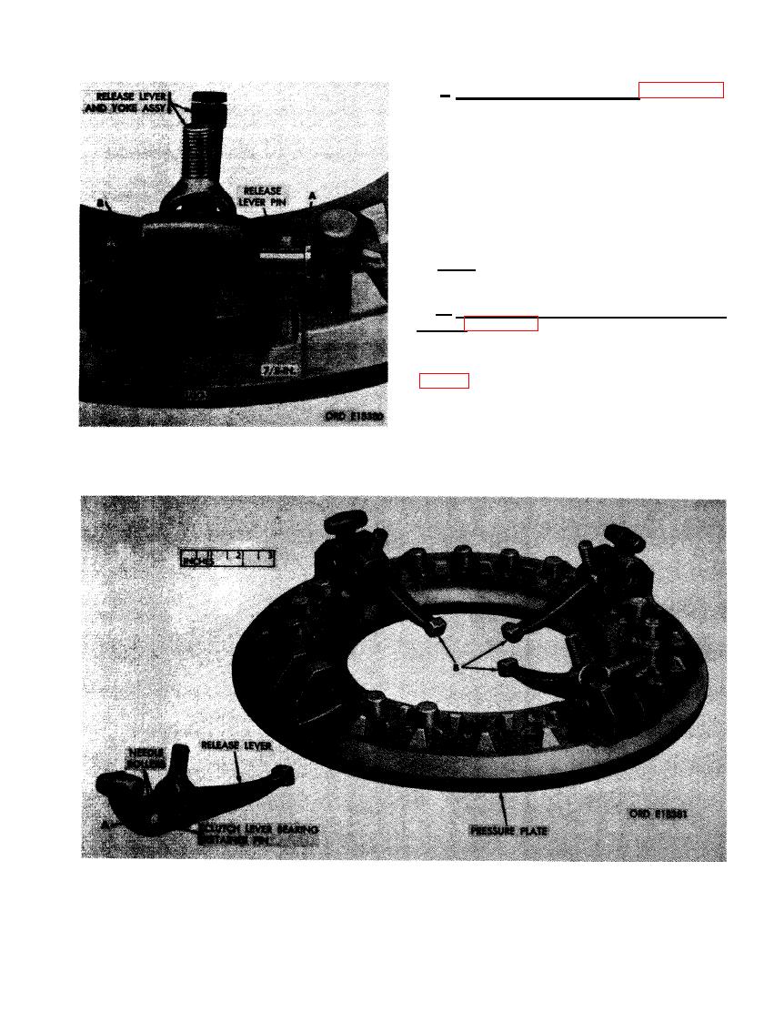 f. Remove Release Lever Pin. Figure 453.
(A) File off mushroomed end of one release
lever pin. Drive pin out of pressure plate lug
and release lever far enough so that distance
from head of release lever pin to machined
surface of pressure plate lug is approximately
7/8-inch. (B) Install clutch lever bearing re-
taining pin through hole in pressure plate lug
and into needle rollers in release lever. Con-
tinueto drive out release lever pinuntil release
lever and yoke assembly can be removed.
Note. Be careful not to lose the 19 needle
rollers when driving out release lever pins.
g. Remove Release Levers and Needle
Rollers. Figure 454. (A) Remove bearing re-
taining pin and 19 needle rollers from release
lever. - (B) Remove the remaining three release
RELEASE LEVER PIN.
289
|
|
Privacy Statement - Press Release - Copyright Information. - Contact Us |
