 |
|||
|
|
|||
|
Page Title:
FIGURE 404. FUEL FILTER ASSEMBLY - EXPLODED VIEW. |
|
||
| ||||||||||
|
|
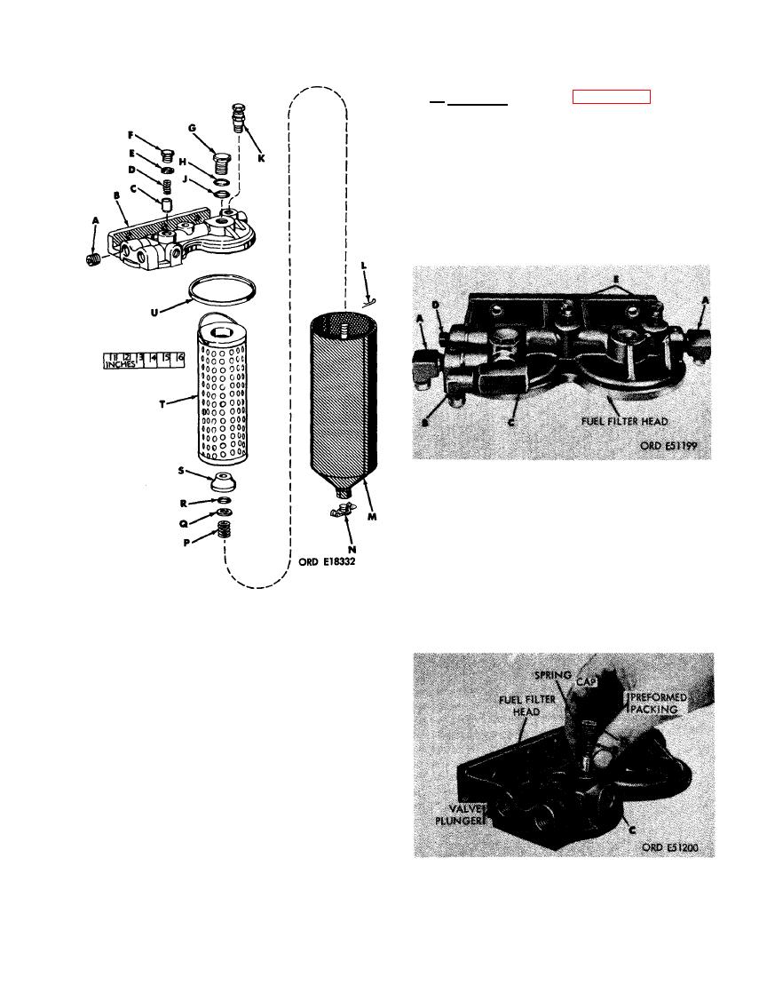 d . Assembly. Refer to figures 405 and 406
a n d- reverse the sequence of illustrations and
instructions to assemble the fuel filter head.
Position element spring (P), washer (Q), new
spring seat packing (R), and spring seat over
stud in fuel filter case (M) in that order. Push
down on spring seat (S) and install pin (L). The
fuel filter elements (T), case gaskets (U), and
fuel filter cases are installed on the fuel filter
head (B) during engine assembly.
FUEL FILTER ELBOWS, TEE, AND VENT
VALVES.
FIGURE 404. FUEL FILTER ASSEMBLY -
EXPLODED VIEW.
in. pipe plug
L-Pin
A - 3/8
B - Fuel filter head
M- Fuel filter case
N - Drain cock
C - Fuel filter relief
valve plunger
P - Element spring
Q - Spring seat
D - Plunger spring
E - Cap gasket
packing washer
F - Relief valve cap
R - Spring seat
packing
G - Case nut
S - Spring seat
H - Flat washer
T - Fuel filter
J - Preformed
element
packing
U - Case gasket
K - Vent valve
FUEL FILTER RELIEF VALVE.
253
|
|
Privacy Statement - Press Release - Copyright Information. - Contact Us |
