 |
|||
|
|
|||
|
Page Title:
FIGURE 407. FUEL INJECTION TUBE ASSEMBLIES, FUEL INJECTION PUMP ASSEMBLY, FUEL HOSES, AND RELATED PARTS - EXPLODED VIEW. |
|
||
| ||||||||||
|
|
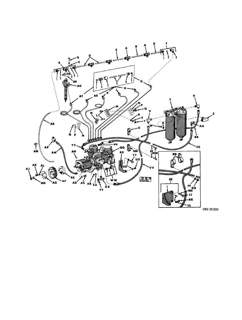 G - Cylinder No. 6 fuel injection tube assembly
7A - Tee assembly
1- 1/2-in. tube sleeve
1- 1/2-in. tube nut
2- 5/8- 18UNF x 1/4 tube fitting
2- l/4-in. tube sleeve
3- Dust cap
3- l/8-27NPTF x l/2-20NF-2A tee
4- 1/4-in. tube
B - 5/16 x 2- 1/2 cap screw
5- 1/2-in. tube nut
C - 5/16-in. lock washer
H - Cylinder No. 5 fuel injection tube assembly
D - 4.380-in. lg plastic tubing
1- 1/4-in. tube sleeve
E - 4.880-in. lg plastic tubing
2- 5/8- 18UNF x 1/4 tube fitting
F - Elbow assembly
3- Dust cap
1- l/2-in. tube nut
4- l/4-in. tube
2- l/2-in. tube sleeve
5- 1/2-in. tube nut
3- l/8-27NPTF x l/2-20NF-2A elbow
FUEL HOSES, AND RELATED PARTS - EXPLODED VIEW.
254
|
|
Privacy Statement - Press Release - Copyright Information. - Contact Us |
