 |
|||
|
|
|||
|
Page Title:
REMOVAL OF ENGINE FROM OVERHAUL STAND FOR COMPLETION OF DISASSEMBLY |
|
||
| ||||||||||
|
|
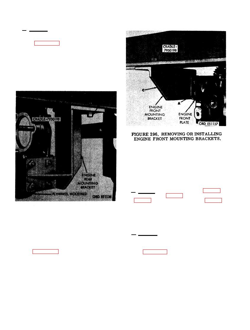 b. Removal. Remove engine mounting brack-
ets as follows.
(1) Figure 295. (A) Remove eight 1/2-inch
plain nuts and 1/2-inch lock washers
securing left and right rear mounting
brackets to engine. (B) Remove two 5/8
x 1-3/4 cap screws and 5/8-inch plain
nuts securing brackets to cradle. (C)
Remove both rear mounting brackets.
STAND FOR COMPLETION OF DISAS-
SEMBLY
a. General. The flywheel housing (fig. 293),
crankshaft assembly (fig. 294), camshaft assem-
bly (fig. 294), and engine front plate (fig. 294)
cannot be removed from the cylinder and crank-
case assembly until engine is removed from
engine overhaul stand - 7950189 and cradle -
7950198.
ENGINE REAR MOUNTING BRACKETS.
b . Removal. Remove engine from cradle -
7950198 as follows.
(2) Figure 296. (A) Remove four 7/16 x
(1) Figure 297. (A) Remove four 5/8-inch
1-3/8 cap screws and 7/16-inch plain
plain nuts, 5/8-inch lock washers, and
nuts securing left and right front mount-
5/8 x 2 capscrews and remove one side
ing brackets to engine. (B) Remove two
rail from cradle assembly. (B) Remove
5/8 x 1-3/4 cap screws and 5/8-inch
overhaul stand and cradle assembly
plain nuts securing mounting brackets
from work area. Reverse the instruc-
to cradle. (C) Remove both front mount-
tions in step A above and install side
ing brackets.
rail on crade assembly.
178
|
|
Privacy Statement - Press Release - Copyright Information. - Contact Us |
