 |
|||
|
|
|||
|
Page Title:
REMOVAL OF ENGINE MOUNTING BRACKETS |
|
||
| ||||||||||
|
|
 143. REMOVAL
OF ENGINE MOUNTING
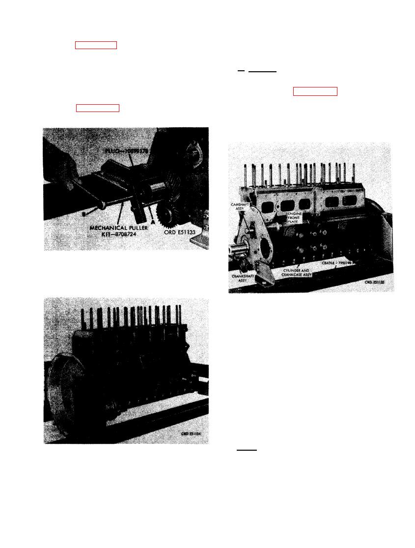
(3) Figure 292. (A) Install 3/8-16 puller
BRACKETS
s c r e w s of mechanical puller kit -
8708724 into puller screw holes in
a. General. The engine must be supported by
crankshaft gear. Insert plug - 10899178
sling - 8715107 and the sling connected to a
against crankshaft and run jack screw
hoist before removing the engine mounting
of puller against plug. (B) Pull crank-
brackets. Refer to figure 294 for a front view
shaft gear from end of crankshaft.
of the stripped engine.
(4) Figure 293 shows the stripped engine
on the overhaul stand.
GEAR USING MECHANICAL
PULLER KIT - 8708724.
FIGURE 294. STRIPPED ENGINE BEFORE
REMOVAL FROM ENGINE OVERHAUL
STAND - 3/4 LEFT FRONT VIEW.
Note. Rotate engine and cradle 180 degrees
(oil pan flange up). Install sling and take up
FIGURE 293. STRIPPED ENGINE BEFORE
slack in sling to support cylinder and crank-
REMOVAL FROM ENGINE OVERHAUL
case assembly before removing mounting brack-
STAND - 3/4 RIGHT REAR VIEW.
ets.
177
|
|
Privacy Statement - Press Release - Copyright Information. - Contact Us |
