 |
|||
|
|
|||
|
Page Title:
REMOVAL OF COMPONENTS FROM RIGHT SIDE OF ENGINE |
|
||
| ||||||||||
|
|
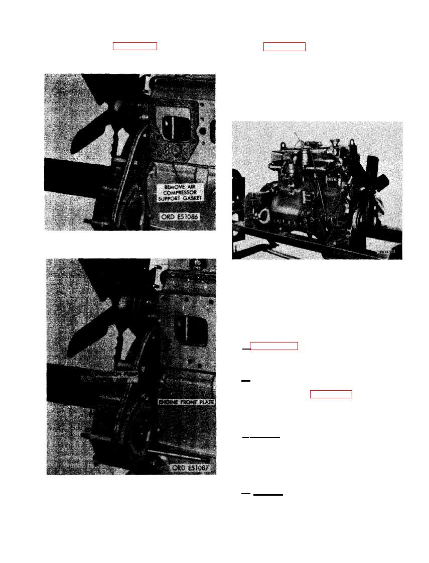 (2) Refer to figure 242 and remove air
(3) Figure 243. (A) Remove two 3/8-inch
compressor support gasket.
plain nuts and 3/8-inch lock washers
securing fuel injection pump adapter
assembly to engine front plate. (B) Re-
move fuel injection pump adapter as-
sembly. (C) Remove and discard fuel
injection pump adapter gasket.
AIR COMPRESSOR SUPPORT GASKET.
FIGURE 244. PARTIALLY STRIPPED
ENGINE IN OVERHAUL STAND - 3/4
RIGHT FRONT VIEW.
122. REMOVAL OF COMPONENTS FROM
RIGHT SIDE OF ENGINE
a . Figure 244 shows the engine partially
disassembled and mounted on overhaul stand -
7950189 and cradle - 7950198.
b . Continue to disassemble the engine by
removing components from the right side fol-
lowing instructions for figures 245 through 256.
123. REMOVAL
FLAME HEATER AND ELBOW
a. General. The intake manifold flame heater
is installed in an elbow mounted on the intake
manifold. Air moving from the turbosuper-
charger to the intake manifold passes through
the elbow and can be heated to aid in starting
the engine in cold weather.
FUEL INJECTION PUMP ADAPTER
b . Removal. Remove the intake manifold
ASSEMBLY.
flame heater and elbow as follows.
157
|
|
Privacy Statement - Press Release - Copyright Information. - Contact Us |
