 |
|||
|
|
|||
|
Page Title:
FIGURE 191. REMOVING OR INSTALLING FRONT CYLINDER HEAD ASSEMBLY. |
|
||
| ||||||||||
|
|
 CYLINDER HEAD ASSEMBLY.
(6) Figure 190. (A) Refer to figure 188 and
(7) Refer to figure 191 and remove the front
remove valve rocker arm push rods.
cylinder head assembly.
(B) Remove three 9/16-inch plain nuts,
and 9/16 id x 3/8 thk special washers on
Caution: Place the front cylinder head
left side of front cylinder head. (C) Re-
assembly on suitable blocks as shown in
move eleven 9/16- inch plain nuts and
9/16 id x 1/8 thk special washer secur-
zle tips extending from the head.
ing front cylinder head to crankcase.
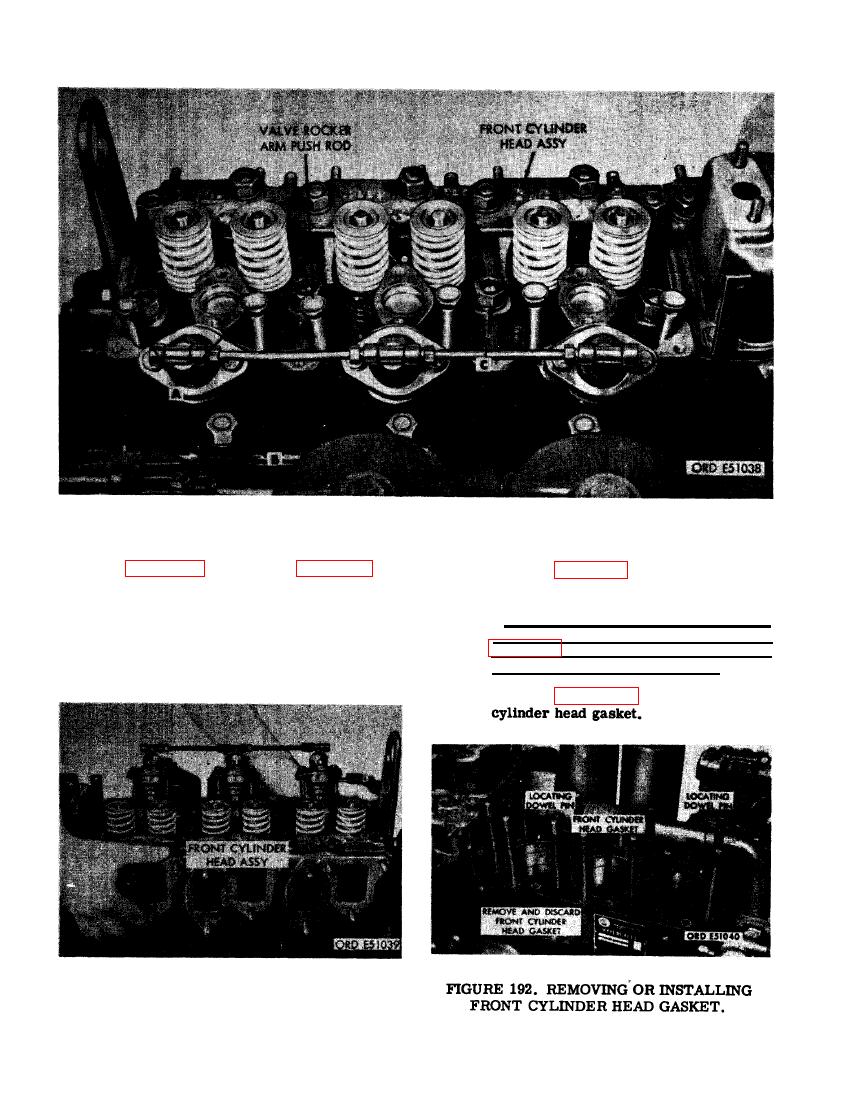
(8) Refer to figure 192 and remove front
FRONT CYLINDER HEAD ASSEMBLY.
128
|
|
Privacy Statement - Press Release - Copyright Information. - Contact Us |
