 |
|||
|
|
|||
|
Page Title:
FIGURE 193. REMOVING OR INSTALLING ENGINE FRONT LIFTING BRACKET AND FUEL RETURN TUBES |
|
||
| ||||||||||
|
|
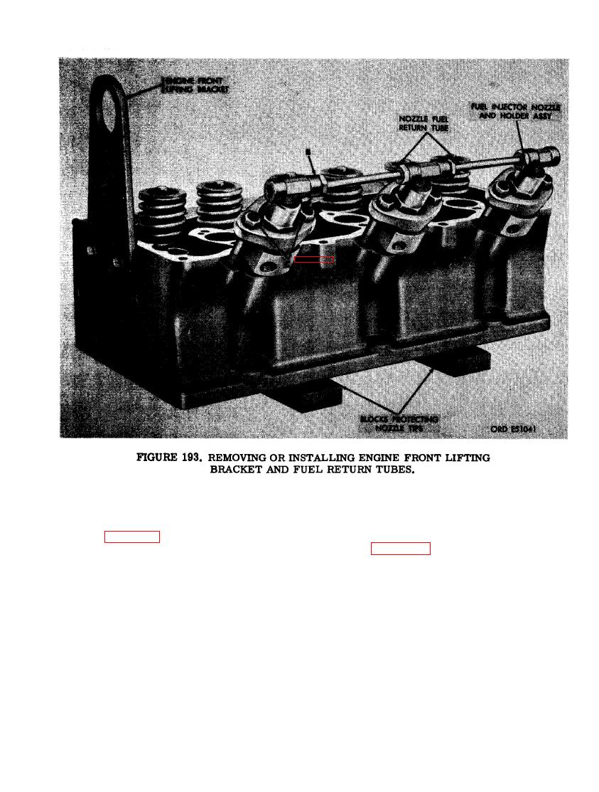 c. Disassemble Disassemble front cylinder
Note. Replacement cylinder heads are
head assembly as fOllows.
furnished complete with valves, springs,
rotators, and retainers.
(1) Figure 193. (A) Remove two 7/16 x 7/8
cap screws and 7/16- inch lock washers
(2) Figure 194. (A) Remove the three fuel
securing engine front lifting bracket to
injector nozzle and holder assemblies
front cylinder head assembly. Remove
from front cylinder head assembly.
bracket. (B) Disconnect the 1/4- inch
(B) Remove and discard the three fuel
tube nuts on the two fuel injector nozzle
injector nozzle-to- head gaskets (C) Re-
fuel return tubes from 1/4-inch tube tees
move 1/4 tube x 1/8 tube tees from each
in fuel injector nozzle and holder assem-
nozzle and holder assembly. Remove
blies. Remove the two tubes from be-
hold-down clamps and note the dowel
tween the tube tees. (C) Remove the two
pin hole in clamp and the locating dowel
5/16 x 2-1/2 cap screws and 5/16-inch
pin in holder. The hold-down clamp
lock washers securing each fuel injec-
must be installed so that the dowel pin
tor nozzle and holder assembly and hold-
will enter hole to properly position noz-
down clamp to front cylinder head as-
zle and holder assembly in cylinder
sembly.
head.
129
|
|
Privacy Statement - Press Release - Copyright Information. - Contact Us |
