 |
|||
|
|
|||
|
Page Title:
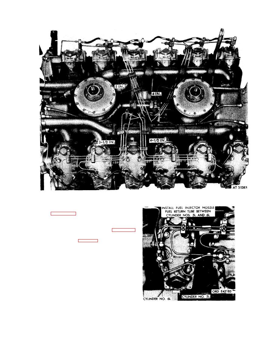
Figure 7-31. Fuel injector clamps, supports, and tube installed view |
|
||
| ||||||||||
|
|
 7-31.
Fuel
injector
clamps,
supports,
and
tubes-installed
view.
e. Fuel Injector Nozzle Fuel Return Tubes.
Refer to figures 5-63 through 5-61.
Note. Install rigid fuel drain tubes only if they
are in a like new condition, otherwise install
current flexible rubber hose as shown in figure 7-
31. The drain tube on hose between cylinder
numbers 6L and 5L (fig. 7-32 or 7-33) will be
noticeably longer than the other drain tubes or
hoses due to the position of the fuel injector
nozzle and holder assembly drain connector.
F i g u r e 7-32. Fuel injector nozzle fuel return
tube between cylinder numbers 6L
7-25
and 5L-engines with tubes.
|
|
Privacy Statement - Press Release - Copyright Information. - Contact Us |
