 |
|||
|
|
|||
|
Page Title:
Figure 5-63. Removing or installing fuel injector nozzle fuel tube connectors and elbow connector-right side. |
|
||
| ||||||||||
|
|
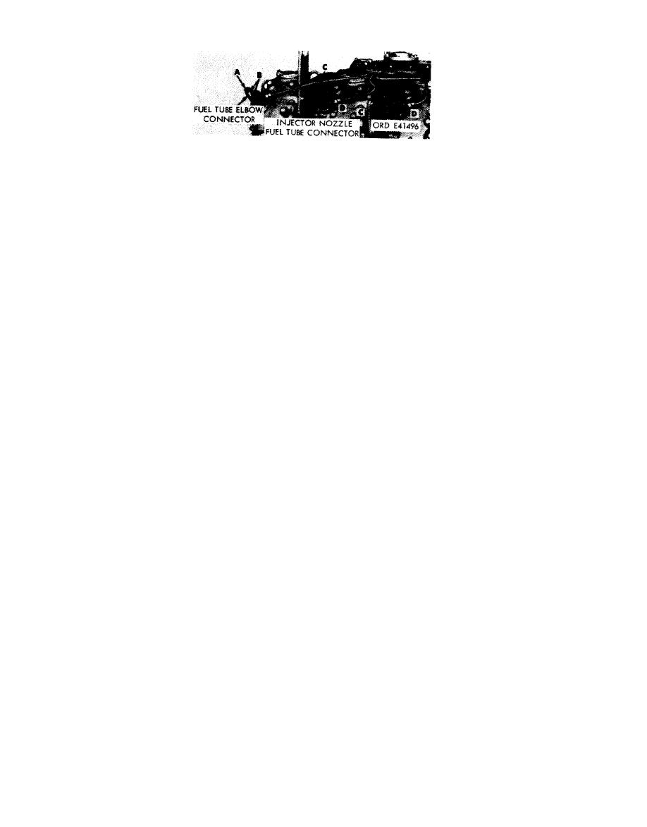 Remove
Install
1. Remove special bolts (A) attaching fuel tube elbow
1. Position a new connector gasket (B) on special bolt
connector to nozzle and holder in cylinder No. 1 R.
(A), insert bolt through fuel tube efbow connector, and
2. Remove and discard elbow connector gaskets (B)
position second new connector gasket (B) on bolt.
from bolt as bolt and elbow connector are separated.
2. Install assembled special bolt (A), with gaskets and
3. Remove five special bolts (C) attaching fuel tube
elbow connector in nozzle and holder at cylinder No.
connectors to nozzle and holder assemblies in cylinder
1R.
Nos. 2R, 3R, 4R, 5R, and 6R.
3. Position a new connector gasket (D) on special bolt
4. Remove and discard connector gaskets (D) from bolts
(C), insert bolt through fuel tube connector, and
as bolt and connector are separated.
position second new connector gasket (D) on bolt.
4. Install five assembled special bolts (C), with gaskets
Note. Fuel injector nozzle fuel tube connectors
and tube connectors in nozzle and holder assemblies at
cylinder Nos. 2R, 3R, 4R, 5R and 6R.
and elbow connectors on left side of engine are
removed or installed in the same manner.
injector nozzle fuel tube connectors and
elbow connector-right side.
5-36
|
|
Privacy Statement - Press Release - Copyright Information. - Contact Us |
