 |
|||
|
|
|||
|
Page Title:
Figure 6-231. Removing or installing heater tube |
|
||
| ||||||||||
|
|
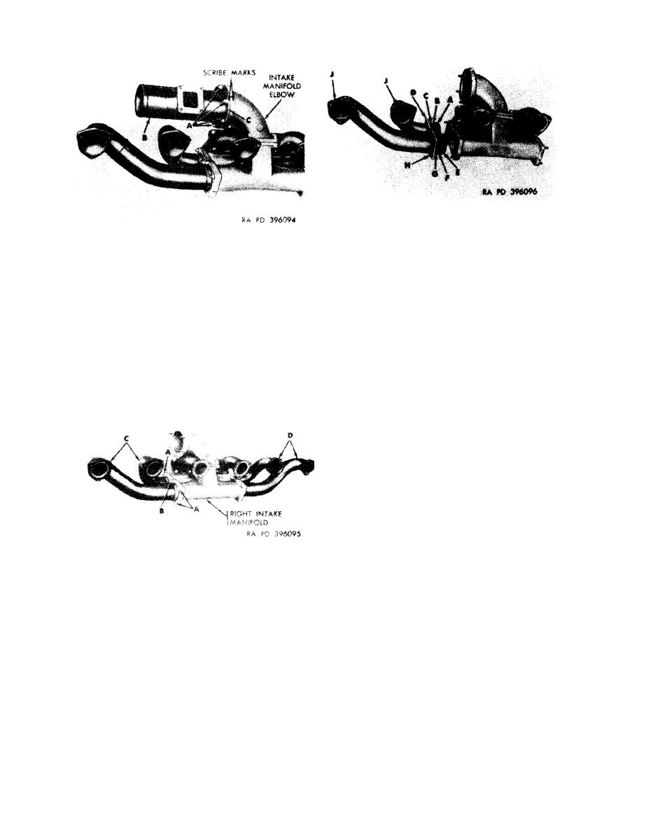 Remove
1. Remove
and discard preformed packing (A).
2. Remove
flat washer (B).
Remove
3. Remove
spring tension washer (C).
Note. Scribe a line across flange of heater tube
4. Remove
small flange (D).
elbow for correct
manifold
intake
and
5. Remove
and discard preformed packing (E).
6. Remove
flat washer (F).
positioning during assembly.
7. Remove
spring tension washer (G).
1. Remove six self-locking nuts (A).
8. Remove
large flange (H).
2. Remove heater tube (B).
3. Remove and discard heater tube gasket (C).
9. Remove flanges (J) from intake manifold tubes.
1 0 . Remove flanges and associated parts from intake
Install
1 . Position a new heater tube gasket (C) on intake
manifold tubes for cylinder Nos. 1R and 2R in the same
manifold elbow.
manner.
2. Position heater tube (B) on elbow with scribe marks
Install
alined.
1 . Install flanges (J) on intake manifold tubes for
3. Install six self-locking nuts (A).
cylinder Nos. 5R and 6R.
Figure 6-231. Removing or installing
2. Position large flange (H) on intake manifold tube for
cylinder No. 6R.
heater
tube.
3. Position spring tension washer (G) on intake manifold
tube for cylinder No. 6R.
4. Position flat washer (F) on intake manifold tube for
cylinder No. 6R.
5 . Position a new preformed packing (E) on intake
manifold tube for cylinder No. 6R.
6. Position small flange (D) on intake manifold tube for
cylinder No. 5R.
7. Position spring tension washer (C) on intake manifold
tube for cylinder No. 5R.
8. Position flat washer (B) on intake manifold tube for
cylinder No. 5R.
9 . Position a new preformed packing (A) on intake
manifold tube for cylinder No. 5R.
Remove
10. Install flanges and associated parta on intake
1. Remove four self-locking nuts (A).
manifold tubes for cylinder Nos. 1R and 2R in the same
2. Remove two self-locking nuts (B) and flat washers.
manner.
3. Separate intake manifold tubes (C) for cylinder Nos.
Figure 6-233. Removing or installing flanges
5R and 6R from right intake manifold.
4. Separate intake manifold tubes (D) for cylinder Nos.
and associated parts from cylinder Nos. 5R
1R and 2R in the same manner.
and 6R intake manifold tubes.
Install
1. Position intake manifold tubes (C) for cylinder Nos.
5R and 6R on right intake manifold.
2. Install two self-locking nuts (B) and flat washers.
3. Install four self-locking nuts (A).
4. Install intake manifold tubes (D) for cylinder Nos. 1R
and 2R in the same manner.
Figure 6-232. Removing or installing intake
manifold
tube
attaching
parts.
6-196
|
|
Privacy Statement - Press Release - Copyright Information. - Contact Us |
