 |
|||
|
|
|||
|
Page Title:
Figure 6-230. Removing or installing air outlet tube and associated parts |
|
||
| ||||||||||
|
|
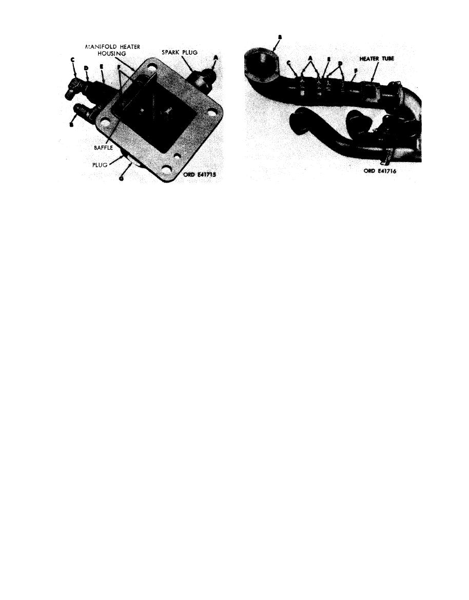 Disassemble
Remove
Note. The right and left manifold heater
1. Loosen two hose clamps (A).
assemblies are similar except for the position of
2. Remove right turbosupercharger air outlet elbow (B).
the spark plug and heater housing plug. The two
3. Remove rubber hose (C) and clamps. Separate two
parts are reversed for the left heater assembly.
clamps from hose.
1. Remove spark plug (A). Remove and discard spark
4. Loosen two hose clamps (D).
plug gasket.
5. Remove air outlet tube (E) from hose.
2. Remove pipe elbow (B).
6. Remove rubber hose (F) and clamps. Separate two
3. Remove pipe elbow (C).
clamps from hose.
4. Remove bushing (D).
Install
5 . Remove manifold heater spray nozzle and holder
1. Position two hose clamps (D) on rubber hose (F).
assembly (E).
Position hose on heater tube.
6. Remove two flat head screws (F) and remove baffle.
2. Position air outlet tube (E) in hose.
3. Tighten two hose clamps (D).
Note. The two screws (F) are staked in place.
4. Position two hose clamps (A) on rubber hose(C).
It may be necessary to remove the stake marks
Position hose on air outlet tube.
before attempting to remove screws.
5. Position right turbosupercharger air outlet elbow (B)
in hose.
7. Remove heater housing plug (G). Remove and discard
6. Tighten two hose clamps (A).
plug gasket.
Figure 6-230. Removing or installing air
Note. Instruction covering housing plug (G)
outlet tube and associated parts.
is applicable only to engines equipped with a
plug.
Assemble
1. On engines equipped with a plug, position a new plug
gasket on heater housing plug (G) and install plug in
manifold heater housing.
2. Position baffle in housing and install two flat head
screws (F). Stake screws in place.
3 . Install manifold heater spray nozzle and holder
assembly (E)
4. Install bushing (D) in holder assembly.
5. Install pipe elbow (C) in bushing.
6. Install pipe elbow (B) in holder assembly.
7. Position a new spark plug gasket on spark plug (A).
Install spark plug in housing.
Figure
6-229.
Disassembling
or
assembling
manifold heater assembly.
6-195
|
|
Privacy Statement - Press Release - Copyright Information. - Contact Us |
