 |
|||
|
|
|||
|
Page Title:
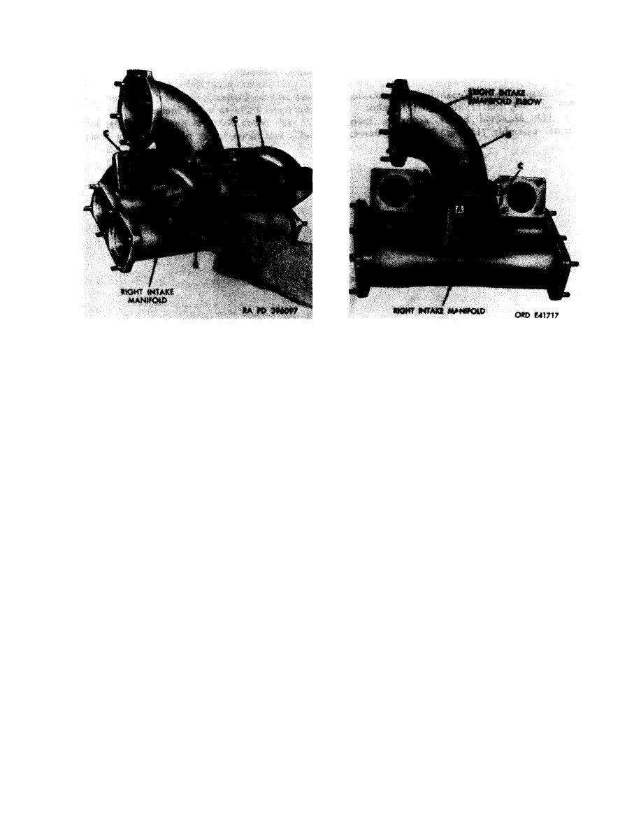
Figure 6-235. Removing or installing right intake manifold elbow. |
|
||
| ||||||||||
|
|
 Remove
1. Remove eight self-locking nuts (A) attaching intake
Note. The right and left intake manifold
manifold tubes for cylinder Nos. 3R and 4R to right
elbows are identical. The position of the left
intake manifold.
intake manifold elbow is 180 degrees opposite
2. Remove intake manifold tubes (B).
from the position of the right elbow.
3. Remove and discard two intake manifold tube gaskets
(C).
1. Remove six seff-locking nuts (A) and flat washers.
Install
2. Remove right intake manifold elbow (B) from right
1. Position two new intake manifold tube gaskets (C) on
intake manifold.
right intake manifold.
3. Remove and discard intake manifold elbow gasket
2. Position intake manifold tubes (B) for cylinder Nos.
(c).
3R and 4R on right intake manifold.
Install
3. Install eight self-locking nuts (A) securing tubes to
1. Position a new intake manifold elbow gasket (C) on
manifold.
right intake manifold.
Figure 6-234. Removing or installing intake
2. Position right intake manifold elbow (B) on right
manifold tubes for cylinder Nos. 3R and 4R.
intake manifold.
3. Install six self-locking nuts (A) and flat washers.
intake manifold elbow.
6-197
|
|
Privacy Statement - Press Release - Copyright Information. - Contact Us |
