 |
|||
|
|
|||
|
Page Title:
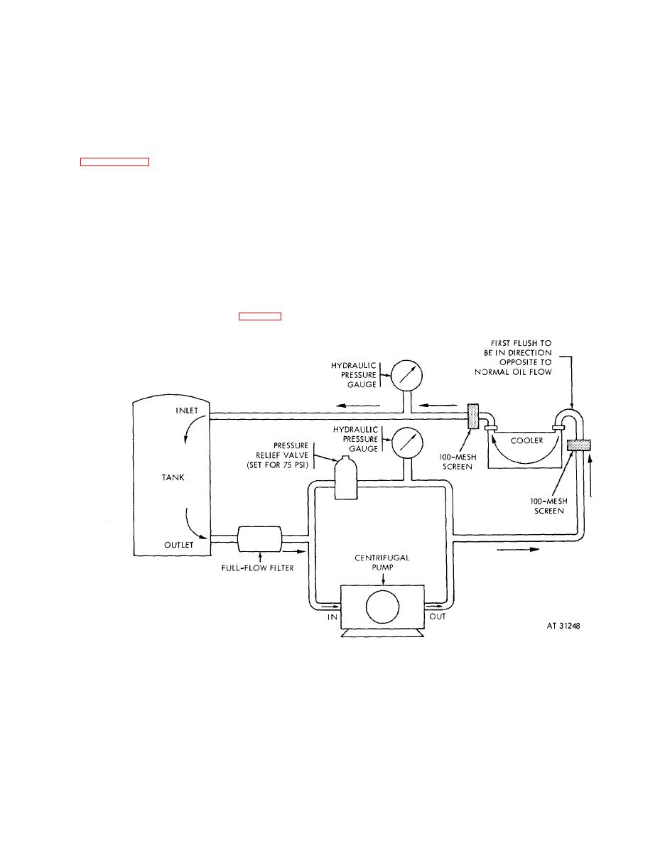
Figure 6-224. Oil cooler cleaning equipment setup-schematic diagram. |
|
||
| ||||||||||
|
|
 rubber
plug
into
bypass
opening
in
the
valve
c.
Cleaning.
housing. Reinstall valve into the valve housing so
(1) External surfaces of coolers may be
that the valve bears up against the rubber plug.
cleaned using oil cooler cleaning tool - 2940-927-
Note. Use only cleaning solutions recom-
3303.
Clean
thoroughly
and
blow
dry
with
mended in these instructions or ones satisfactory
compressed air at 15 psi pressure.
for aluminum. Many solutions satisfactory for
(2) To clean the interior of an oil cooler
cleaning copper or copper nickel coolers are
assembly core, the pump equipment shown in
highly corrosive to aluminum and if used will
result in the destruction of the cooler. If
for the cleaning procedure. There are several
equipment has been previously used with any
possible arrangements of the equipment
other cleaning solutions, it should be thoroughly
depending upon equipment availability and
washed out and flushed with the recommended
versatility. If provision can be made for flushing
solution.
pump lines, one set of pump equipment can be
Warning; Cleaning
solvents
and
solvent
used with four storage tanks to provide the
required four solutions for rinsing, cleaning, a n d
cleaning compounds are toxic and flammable
and must be used only in a well ventilated room.
flushing. If such provisions cannot be made
Take adequate safe guards for fire prevention in
conveniently, four sets of pump equipment are
work area. Use protective clothing and
avoid
required.
contact of these solutions with the skin.
(3) Remove the thermostatic bypass valve
(A) from the valve housing (fig. 6-223). Press a
6-187
|
|
Privacy Statement - Press Release - Copyright Information. - Contact Us |
