 |
|||
|
|
|||
|
Page Title:
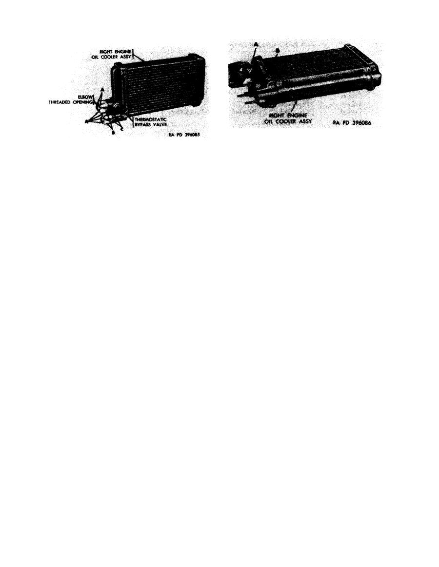
Figure 6-223. Removing or installing engine right oil cooler thermostatic bypass valve. |
|
||
| ||||||||||
|
|
 Remove
1. Remove thermostatic bypass valve (A) from oil cooler.
Remove
2. Remove and discard valve gasket (B).
Note. The
right
and
left
engine
oil
cooler
Install
assemblies are similar except for the position of
1. Position a new valve gasket (B) on oil cooler.
the hose connector elbows. On the right oil cooler
2. Install thermostatic bypass valve (A) in oil cooler.
assembly the threaded openings on the elbows
face away from the engine oil cooler thermostatic
right oil cooler thermostatic bypass valve.
bypass valve. On the left oil cooler assembly, the
threaded openings on the elbows face toward the
engine oil cooler thermostatic bypass valve.
1. Remove six self-locking nuts (A).
2. Remove two hose connector elbows (B).
3. Remove and discard two hose connector elbow gasket
(C).
Install
1. Position two new connector elbow gaskets (C) on oil
cooler assembly.
2. Position two hose connector elbows (B) on oil cooler.
3. Install six self-locking nuts (A).
Figure 6-222. Removing or installing engine
right
oil
cooler
hose
connector
elbows.
6-186
|
|
Privacy Statement - Press Release - Copyright Information. - Contact Us |
