 |
|||
|
|
|||
|
Page Title:
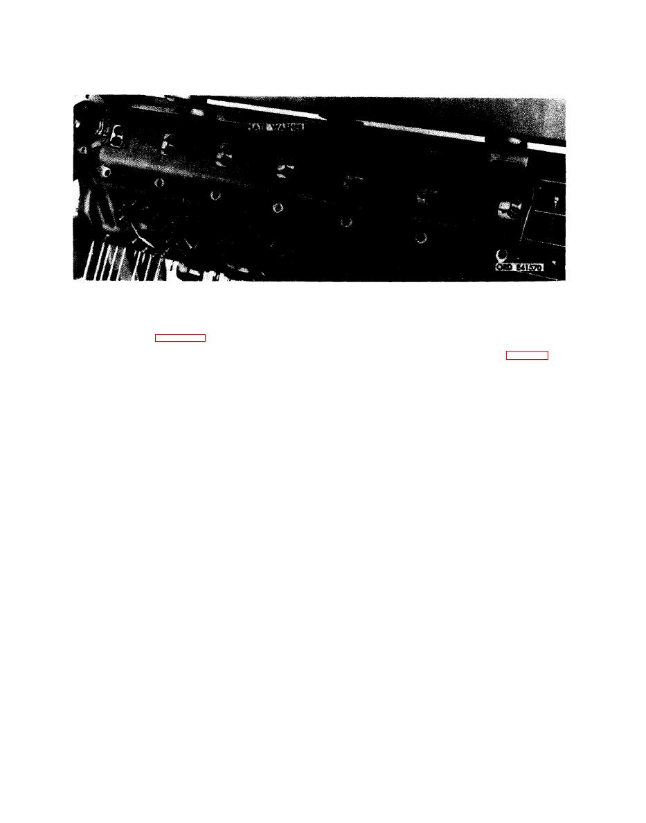
Figure 5-171. Removing or installing crankcase tie rod attaching parts-right front view. |
|
||
| ||||||||||
|
|
 4. Using a suitable brass rod, push the 13 tie rode (D)
Remove
through crankcase assembly.
Install
d r i v e n gearshaft (fig. 5-172), it is necessary to
Note. Do not install the 14 cotter pins until tie
r e m o v e lower No. 7 main bearing crankcase tie
rod nuts have been torque tightened (para 7-6c).
r o d from right side of crankcase.
1. Push the 13 tie rods (D) through crankcase assembly.
1. Remove 12 cotter pins, slotted nuts (A), and six plate
2. Install slotted nut on opposite (left) side of lower tie
washers from 12 crankcase tie rods (D). Hold tie rod
rod (C).
nuts on opposite ends as necessary to keep rods from
3. Install slotted nut (B) on upper tie rod.
turning while removing the nuts.
4. Install six plate washers and 12 slotted nuts (A) on 12
2. Remove cotter pins and slotted nut (B) from upper tie
crankcase tie rods (D).
rod.
3. Remove cotter pin and slotted nut from opposite (left)
side of lower tie rod (C).
p a r t s - r i ght front view.
5-98
|
|
Privacy Statement - Press Release - Copyright Information. - Contact Us |
