 |
|||
|
|
|||
|
Page Title:
Figure 5-151. Removing or installing fuel pump drive coupling adapter and coupling. |
|
||
| ||||||||||
|
|
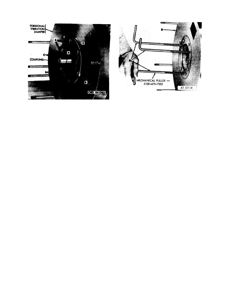 1. Install three mechanical pullers (A) - 5120-473-7222
into puller screw boles provided in crankshaft torsional
Remove
vibration damper.
1. Cut locking wire (A).
2. Alternately tighten puller screws and pull damper (B)
2. Remove six drilled head bolts (B) attaching fuel pump
from dowel pine in flange of crankshaft. Remove
drive coupling adapter and crankshaft torsional
damper.
vibration damper to crankshaft.
3. Remove adapter and fuel pump drive coupling (C).
Install
vibration damper using mechanical
1. Position fuel pump drive coupling adapter and fuel
p u l l e r s - 5120-473-7222.
pump drive coupling (C) on crankshaft.
2. Install six drilled head bolts (B) securing adapter and
crankshaft torsional vibration damper to crankshaft
3. Install locking wire (A) securing bolts.
pump drive coupling adapter and coupling.
5-87
|
|
Privacy Statement - Press Release - Copyright Information. - Contact Us |
