 |
|||
|
|
|||
|
Page Title:
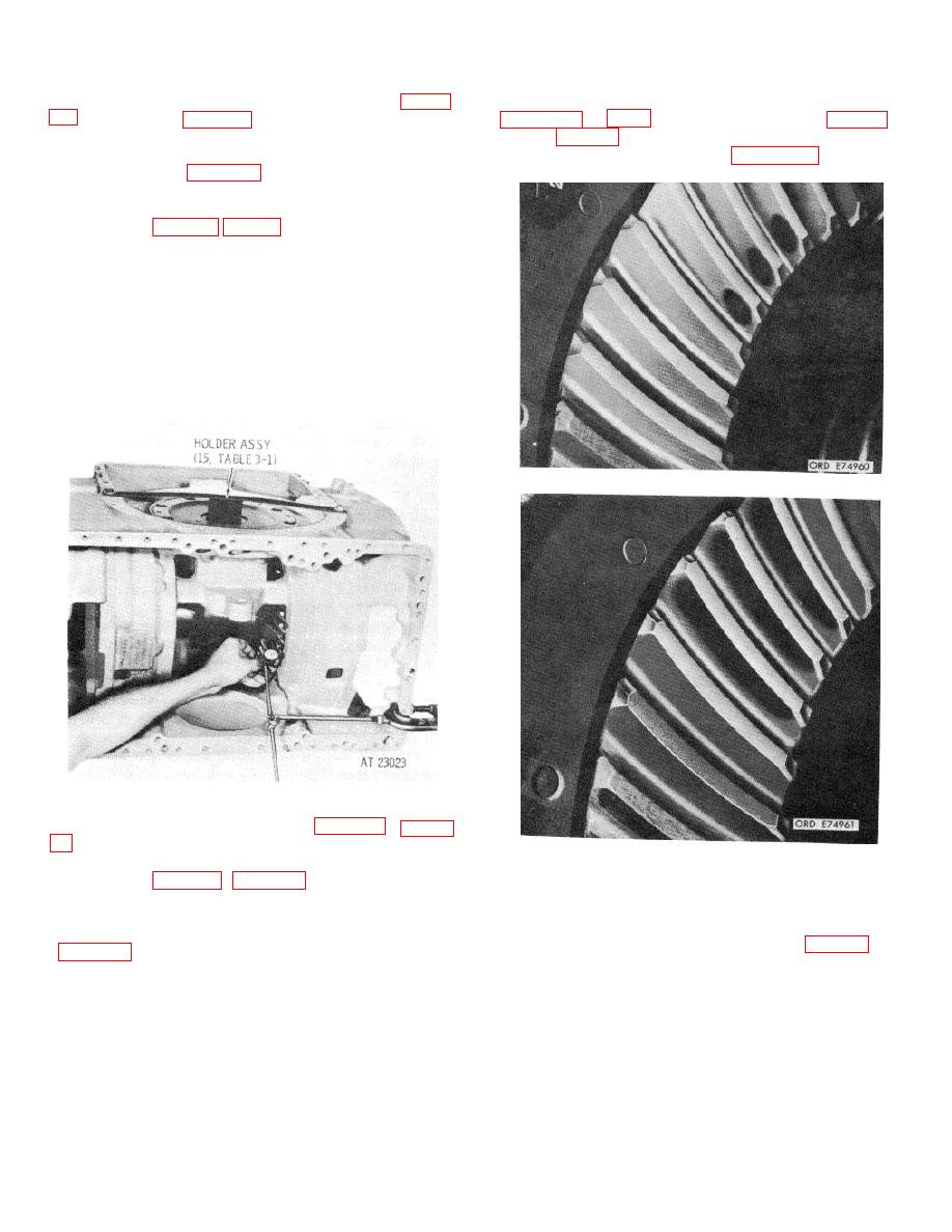
Figure 8-5. Checking backlash of bevel gears. |
|
||
| ||||||||||
|
|
 TM 9-2520-249-34&P
preload are properly adjusted, install shim pack Z (fig. 8-
pattern and compare it with the patterns shown in
gear assembly into the bevel gear housing. Tighten the
and Z (fig. 8-2), as required, to establish the proper
bolts which retain the assembly, Check the free rotation
pattern. Recheck the backlash. Figure 8-7 illustrates
of the bevel gears (para 8-11, step 8, below).
the proper gear tooth contact pattern under full load.
b. Check the backlash between the drive and
driven gear teeth by locking the drive gear with holder
assembly (15, table 3-1) (fig. 8-5). Install a dial indicator
against a tooth of the driven gear. Rock the driven gear
in both directions and note the backlash. It should be as
indicated by the etched dimension (BL) on the gear set.
NOTE
Backlash may be adjusted by changing shim
pack Z, or by moving shims from shim pack X
to shim pack Y or vice versa. However, any
change in shimming will affect the gear tooth
contact pattern and must be coordinated with
adjustments outlined in c, below.
Figure 8-6. Gear tooth contact pattern-no load.
Figure 8-5. Checking backlash of bevel gears.
Figure 8-7. Gear tooth contact pattern-full load.
fairly dry mixture of red lead and oil. Using wrench
assembly (30, table 3-1) (para 8-11, step 8, below), and
8-9.
Determining Nominal Shim Between Brake
a socket wrench drive, rotate the drive gear in a
Coolant Pump Body and Drive Gear Bearing
clockwise direction through several revolutions while
holding a light load against turning of the cross shaft
the pump drive gear bearing.
8-4
|
|
Privacy Statement - Press Release - Copyright Information. - Contact Us |
