 |
|||
|
|
|||
|
Page Title:
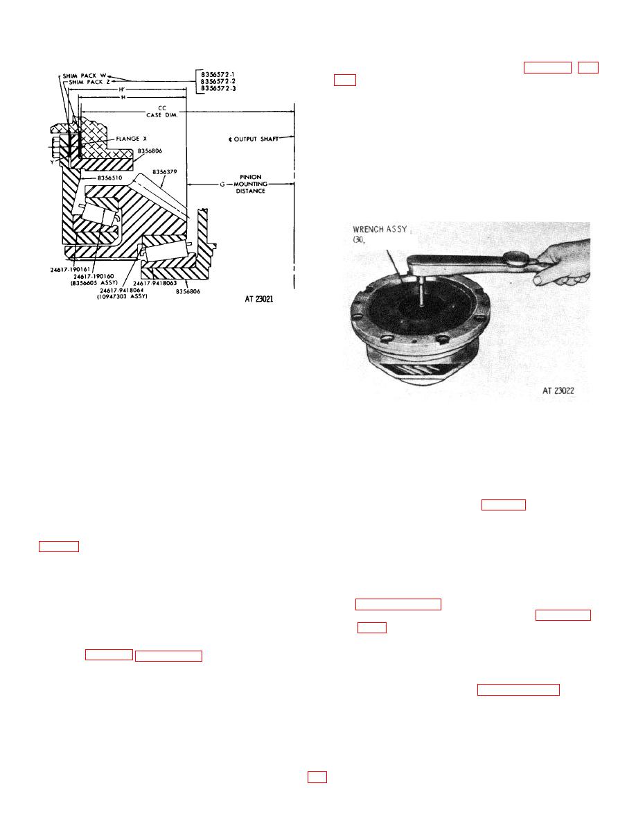
Determining Actual Shim Between Bevel Drive Gear Support and Carrier |
|
||
| ||||||||||
|
|
 TM 9-2520-249-34&P
check the torque required to slowly rotate the
bevel drive gear within the carrier. At zero end play,
torque should not exceed 2 pound inches. If greater
than this figure, add shims to increase the end play - but
do not let the end play exceed 0.0015 inch.
NOTE
If trouble is encountered in arriving at an
adjustment that is within both the torque
and end play limits, disassemble the parts
and inspect the bearings for dirt. Clean
them and lubricate with recommended
transmission fluid.
TABLE 3-1
Figure 8-2. Nominal shims for bevel drive gear support
and carrier.
b. Position gear 8356379, teeth upward, on a
level surface. Position the assembled carrier 8356806,
larger diameter down, over gear 8356379. Rotate the
carrier to seat bearing assembly 10947303 firmly.
c. Measure and record the vertical distance
Figure 8-3. Checking preload torque of bevel drive gear
H, from the flange surface of carrier 8356806 to the end
surface of gear 8356379.
d. Measure and record the thickness of flange
8-5.
Determining Nominal Shim B etween Bevel
X.
Drive Gear Carrier and Transmission
e. Position the support 8356510, bearing
Housing
upward, on a level surface.
f.
Remove carrier 8356806 from gear
8356379. Install the gear, teeth upward, on support
bevel drive gear in approximately the correct relation to
8356510. Rotate it to seat bearing 8356605 firmly.
the bevel driven gear's installed position.
g. Measure and record the vertical distance H'
b. Calculate
shim
Z
by
substituting
dimensions previously recorded for H, G and CC, in the
the end surface of gear 8356379.
formula Z = H + G - CC.
h. Substituting the dimensions obtained in c, d
NOTE
and g, above, in the formula W = H'-(H + X), calculate
Dimension H was measured and recorded in
the thickness of nominal shim pack W. Select the
proper combination of shims 8356572 1, 8356572 2 and
were recorded, per instructions in paragraph
8356572 3 which most nearly equals the dimension
8 -2d, above.
obtained for W.
c. Select the proper combination of shims
i.
Assemble the bevel drive gear assembly as
8356572 1, 8356572 2 and 8356572 3 which will most
outlined in chapter 7, section XIV.
nearly equal dimension Z.
d. Do not install the bevel drive gear
8-4.
Determining Actual Shim Between Bevel
assembly until procedures in paragraphs 8 6 and 8-7,
Drive Gear Support and Carrier
following, are completed.
a. When assembly of the bevel drive gear
assembly is completed, check the end play of the gear.
It should not exceed 0.0015 inch. If end play exceeds
this amount, remove shims to reduce it. Reassemble
the gear, carrier and support.
|
|
Privacy Statement - Press Release - Copyright Information. - Contact Us |
