 |
|||
|
|
|||
|
Page Title:
CHAPTER 8. ASSEMBLY OF TRANSMISSION FROM SUBASSEMBLIES |
|
||
| ||||||||||
|
|
 TM 9-2520-249-34&P
CHAPTER 8
ASSEMBLY OF TRANSMISSION FROM SUBASSEMBLIES
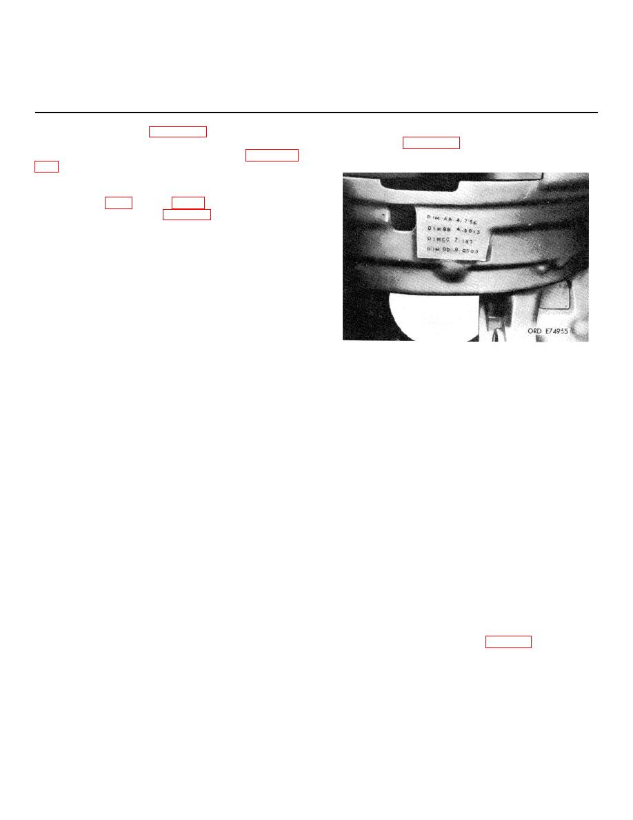
called "case" dimensions and are specific for each bevel
8-1.
Arrangement of Chapter 8
gear housing. Figure 8-1 shows the location of case
Assembly procedures for the transmission, arranged in
dimensions.
consecutive, pictorial steps, commence with paragraph
the bevel gears are given in the paragraphs immediately
following. Also, references will be made to exploded
to special tool information (chapter 3), as needed.
8-2.
Shimming and Adjusting Bevel Gears
a. Matched Components.
(1) The bevel drive gear, bev l driven
e
gear, and brake coolant pump bevel drive gear are
matched components in a set and must be properly
positioned and adjusted in relation to each other.
Correct backlash, gear tooth contact and bearing
preload must be established during assembly of the
transmission.
(2) Steel shims of various thickness are
used to position the gears and to produce the proper
Figure 8-1. Case dimensions stamped on bevel gear
preload on the tapered roller bearings on which the
housing.
bevel drive gears and cross shaft are mounted.
b. Shimming Outlined. The instructions which
(2) Other dimensions must be accurately
follow outline the procedures required to do the
measured during adjustment procedures. The mounting
complete job of shimming and gear setting. However,
dimensions (MD) etched on the gears, the case
when a transmission is rebuilt, the extent of the job will
dimensions and the dimensions measured during
be determined by the extent of factors which prevent
adjustment are all used in the formulas for determining
using the original shim packs.
the nominal (approximate) shim pack thicknesses.
c. When to Use New Shims. Some of the
e. Shimming Illustrated.
Line drawings
factors which prevent using the original shims are:
illustrate each major step in determining the nominal
(1) Evidence of incorrect setting of gears
shim pack thicknesses.
in previous assembly. This can be recognized by
f.
Record Prior to Adjustments. Record all
abnormal gear contact wear pattern.
backlash, mounting distance and case dimensions
(2) Loss or mixing of shims removed
before beginning the gear-setting procedures.
during disassembly. Always tie each shim pack together
g. Final Adjustments. After the nominal shim
at the time of removal and identify its location. As
packs are determined, the gear setting and bearing
added precaution, record the thickness of each shim
preload must be further adjusted to obtain the proper
pack and its location.
backlash, gear tooth pattern and drag torque
(3) Replacement of any components
characteristics.
which, because of manufacturing tolerances, will not be
dimensionally identical to original components.
8-3.
Determining Nominal Shim Between Bevel
d. Stamped and Etched Dimensions.
Drive Gear Support and Carrier
(1) Each gear set is matched during
manufacture and etched with a gear set number,
approximately zero end play of the bevel drive gear
prescribed backlash (BL), and mounting dimension
within its carrier and support.
(MD). Lettered dimensions AA, BB, CC and DD are
tamped on a web in the bevel gear housing. These are
8-1
|
|
Privacy Statement - Press Release - Copyright Information. - Contact Us |
