 |
|||
|
|
|||
|
Page Title:
Section XXVIII. BRAKE COOLANT PUMP ASSEMBLY-REPAIR |
|
||
| ||||||||||
|
|
 TM 9-2520-249-34&P
Table 7-23. Repair Standards (Input Oil Pump)-Continued
Wear limit
Reference
Size and fit
DS/GS
Foldout
Item
Point of measurement
of new parts
maintenance
11
22a
Outside diameter at bearing surface of gear 0.6245 to 0.6250
0.6242
shaft
11
25a
Inside diameter at bearing surface of body 0.8068 to 0.8075
0.8080
11
27a
Outside diameter of bearing .................
To press fit 0.8075
*
to 0.8078 bore
11
25a,
Fit of bearing in body............................
0.0000 to 0.0010T
27a
*Replace when worn beyond new dimensions.
Section XXVIII. BRAKE COOLANT PUMP ASSEMBLY-REPAIR
e. Do not remove needle bearing (57) from
7-164. Description
pump cover (58) unless replacement is necessary.
Refer to paragraph 2-19 for description of the brake
f.
Do not remove two dowel pins (56) from
coolant pump components.
pump cover (58) unless replacement is necessary.
g. Remove two driven gear assemblies (51,
7-165. Disassembly
h. Remove two driven gear shafts (49) and
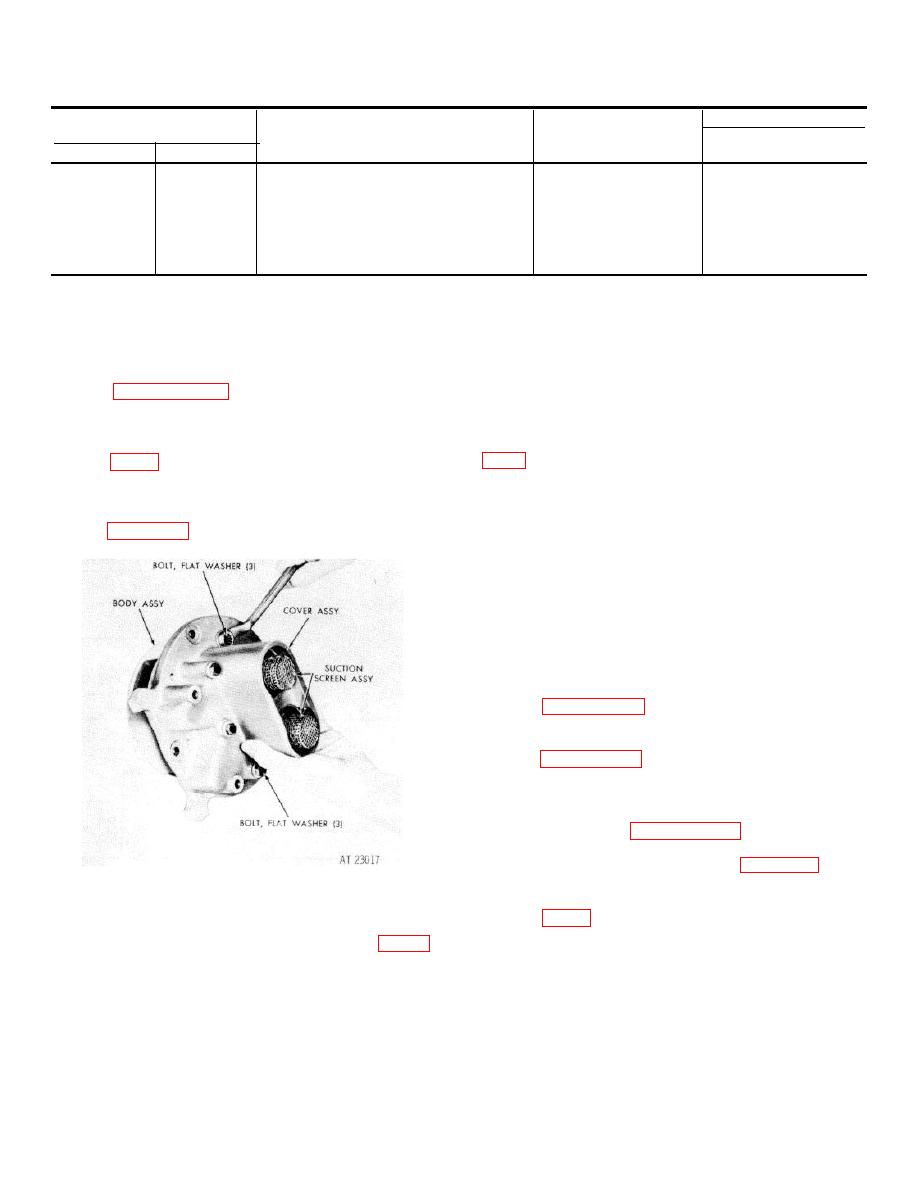
a. Remove three bolts (68), three bolts (70)
two antirotation balls (50) from pump body (46).
and six flat washers (67 and 69). Remove coolant pump
i.
Remove two retaining nuts (41) from
cover assembly (55) from pump body assembly (44).
internal drive gears (48) and remove two external-driven
Refer to figure 7-56.
gears (42).
j.
Remove four thrust washers (43) from
internal drive gears (48).
pump body (46).
l.
Do not remove needle bearing (45 and 47)
unless replacement is necessary.
7-166. Cleaning
Refer to paragraph 5-2 for cleaning recommendations.
7-167. Inspection and Repair
Refer to paragraph 5-3 for general inspection and repair
recommendations.
7-168. Repair Standards
repair standards.
Figure 7-56. Removing (or installing) brake coolant
7-169. Assembly
pump cover assembly bolt.
a. If needle bearing (45) were removed from
pump body (46), press new replacements flush with, to
and two coolant suction screen assemblies (65).
0.005 inch below, the outer surface of the pump body.
c. Remove six washers (60, 62, 64), two
Press against the numbered side of the bearing cage.
check valve guide pins (59), and two springs (61) from
b. If needle bearing (47) was removed from
pump cover (58).
pump body (46), press a new replacement 0.18 inch
d. Do not remove two grommets (63) from
below the surface adjacent to the bearing bore.
washers (62 and 64) unless replacement is necessary.
7-51
|
|
Privacy Statement - Press Release - Copyright Information. - Contact Us |
