 |
|||
|
|
|||
|
Page Title:
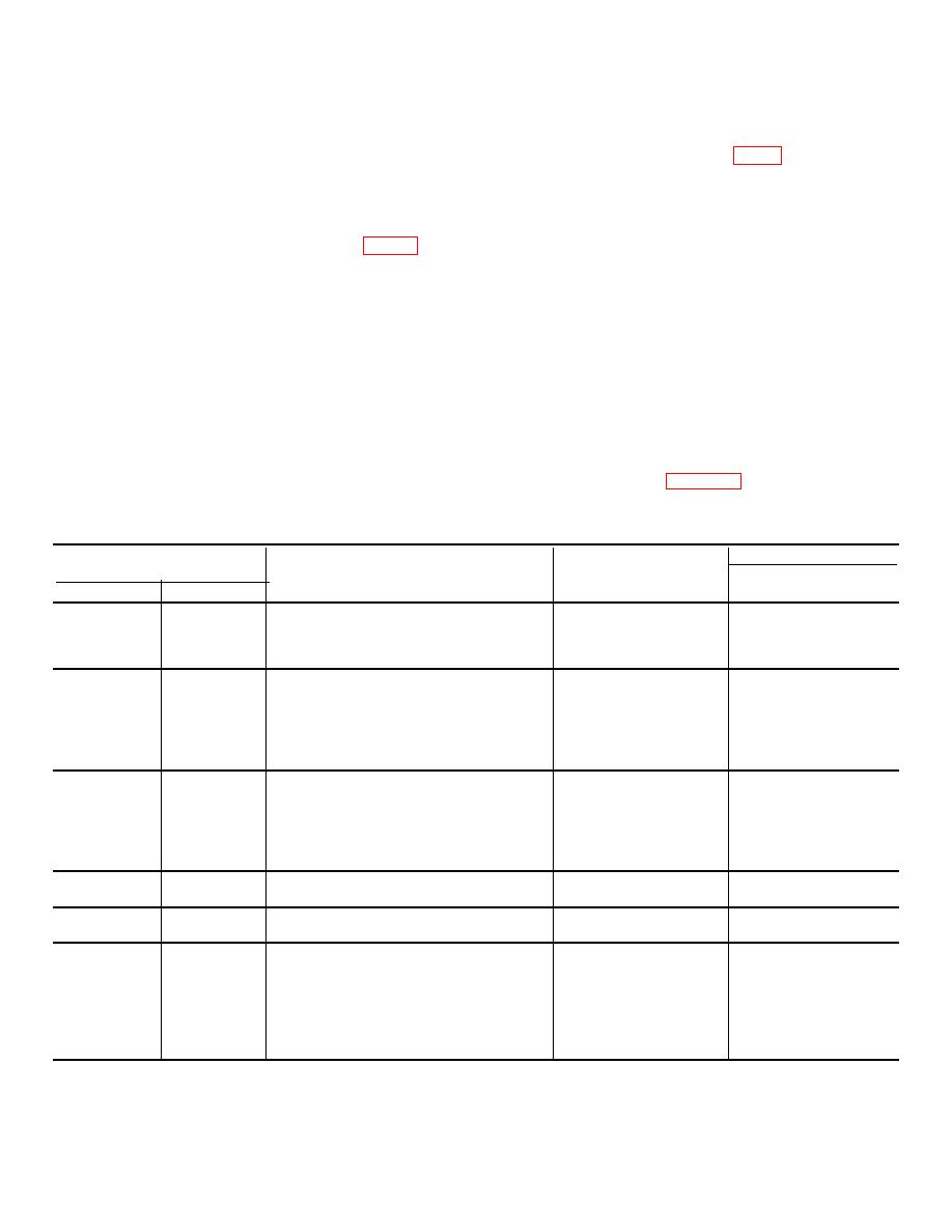
Table 7-24. Repair Standards (Brake CooIant Pump) |
|
||
| ||||||||||
|
|
 TM 9-2520-249-34&P
c. Install two internal drive gears (48) into
j.
If dowel pins (56) were removed from
pump body (46).
pump cover (58), install new replacements. Install pins
d. Install four thrust washers (43) onto two
to 0.300 inch above the surface of the cover.
internal drive gears (48).
e. Install two external-driven gears (42) onto
first, into pump cover 158).
I.
Install a spring (61) onto each pin (59).
two internal drive gears. Secure the external driven
gears with two nuts (41). Tighten the nuts to 30 to 32
m. Install a washer (60) onto each pin.
pound feet torque.
n. Install a grommet (63) on each pair of
f.
Place antirotation balls (50, FO-11) on
washers (62 and 64).
driven gear shafts (49) and retain them with oil-soluble
o. Install each pair of washers (62 and 64)
grease. Install the shafts, with the balls, into pump body
with grommet (63) onto each pin (59). The steel
(46).
washers (62) must be upward, against spring 161).
p. Install two screen assemblies (65) into
driven gears (53), install new replacements. Install each
pump cover (58) and secure each screen with a
bearing, pressing against the numbered side of the
retaining ring (66).
bearing cage, 0.006 inch below the end surface of each
q. Install the pump cover assembly and
gear.
attached parts onto pump body assembly (44). Secure
h. Install two driven gear assemblies (51) onto
the two assemblies with three 5/16-18 x 1 1/8-inch bolts
driven gear shafts (49).
(68) and flat washers (67). Tighten the bolts to 13 to 16
i.
If needle bearings (57) were removed from
pound feet torque. Install three 5/16-18 x 2 3/4-inch
pump cover (58), install new replacements. Install the
bolts (70) and flat washers (69). Tighten the bolts to 17
bearings, pressing against the numbered side of the
to 20 pound feet torque (fig. 7-56)
cage, 0.050 inch below the surface of the cover.
Table 7-24. Repair Standards (Brake CooIant Pump)
Wear limit
Reference
Size and fit
DS/GS
Foldout
Item
Point of measurement
of new parts
maintenance
11
38b
Outside diameter of bearing .................
2.0467 to 2.0472
*
11
46a
Inside diameter at bearing surface of body
2.0471 to 2.0481
2.0486
11
38b,
Fit of bearing in body ...........................
0.00011T to 0.0014L
46a
11
45a
Outside diameter of bearing .................
To press fit 0.8075
*
to 0.8078 bore
11
46b
Inside diameter at bearing surface of body 0.8075 to 0.8080
0.8085
11
45a,
Fit of bearing in body............................
0.0005L to 0.0003T
46b
11
46c
Inside diameter at bearing surface of body
1.0615 to 1.0625
1.0630
11
47a
Outside diameter of bearing To press fi
1.0620
*
to 1.0630 bore
11
46c,
Fit of bearing in body............................
0.0005L to 0.0015T
47a
11
48a
Outside diameter at bearing surface of gear 0.6245 to 0.6250
0.6242
11
49a
Outside diameter of shaft ....................
0.6245 to 0.6250
0.6242
11
52a.
Outside diameter of bearings To press fit
0.8075
*
54a
to 0.8078 bore
11
53a
Inside diameter of gear ....................... .
0.8075 to 0.8080
0.8085
11
52a,
Fit of bearing in gear ...........................
0.0005L to 0.0003T
53a,
54a
7-52
|
|
Privacy Statement - Press Release - Copyright Information. - Contact Us |
