 |
|||
|
|
|||
|
|
|||
| ||||||||||
|
|
 TM 9-2520-246-34
k. Transfer Top Cover and Shifter Shaft.
i. Case Cover.
NOTE
NOTE
When assembling, use a new gasket and
Use care not to damage or lose taper pins
install new lockwire. Tighten capscrews and
during removal since they are non-supply
lockwashers to 22-28 lb-ft torque.
items and must be fabricated if lost or
damaged.
Remove the four capscrews and lockwashers
securing the top cover to the transfer case. (See fig. 4-
(1) Polish the end of the shifter shaft to remove
33). Remove the top cover and top cover gasket.
roughness and paint. (See fig. 4-31.) Remove the 18
Discard the gasket. Remove the shifter shaft spring,
capscrews, nuts, and lockwashers securing the case
plunger, and ball. (See fig. 4-34.) Using a pair of wire
cover to the case. Remove the three taper pins from
cutters, remove the lockwire from the fork setscrew.
the case and cover, with a drift or punch.
Remove the setscrew, then remove the shifter shaft
NOTE
from the fork assembly.
l. Input Shaft Assembly, Fork Assembly, and Idler
Install taper pins, install new gasket, aline
Shaft Assembly. Using a soft drift pin and hammer,
case cover with taper pins, and tighten nut
drive the input shaft assembly, fork assembly, and
and capscrews evenly and alternately.
idler shaft assembly from the transfer case.
Tighten capscrews marked Y and W to 60-
77 lb-ft torque. Tighten remaining
capscrews marked Z to 67-87 lb-ft torque.
(2) Install puller screws in the two puller-screw
holes located in the flange of the case cover. (See fig.
and tap on the end of the shifter shaft with a mallet.
Lift the cover assembly from the case. Remove and
discard the gasket. Remove the outer thrust washer
from the input shaft.
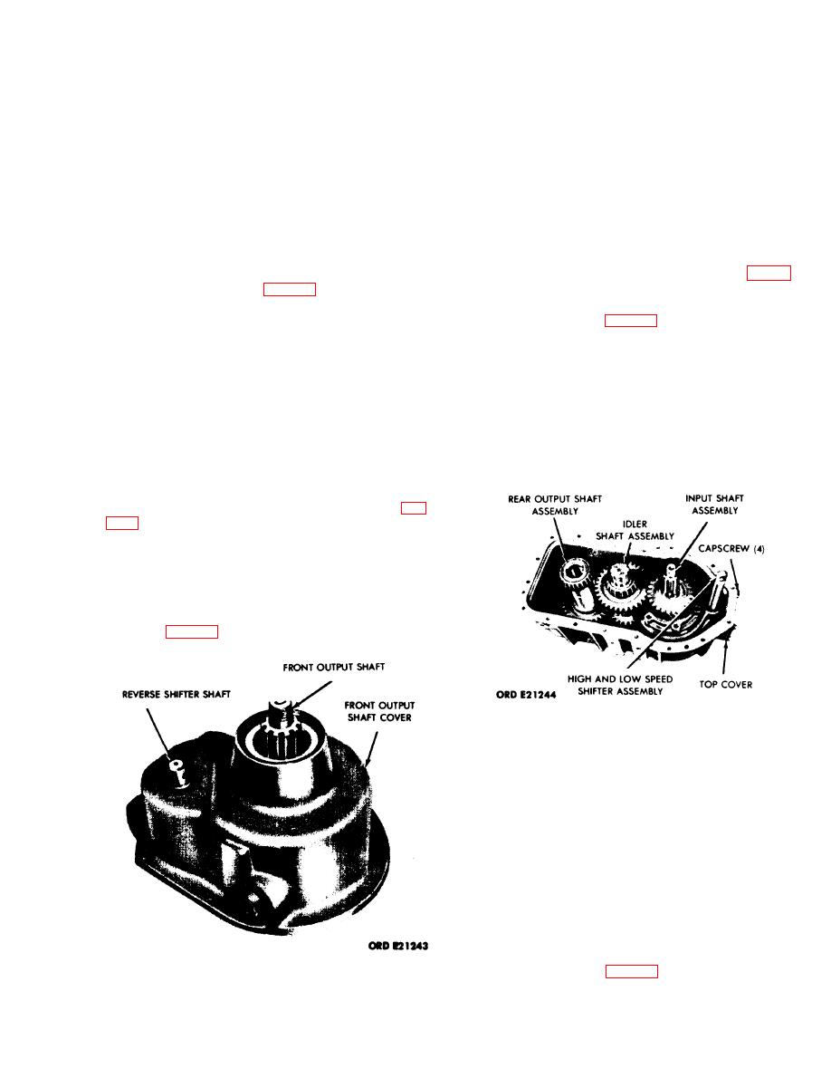
j. Rear Output Shaft Assembly. After the case
cover has been removed, lift the rear output shaft
assembly (fig. 4-33) from the transfer case.
Figure 4-33. Removal of Rear Output, Idler, and
Input Shaft Assemblies
m. Rear Output Shaft Rear Bearing Cover.
NOTE
When assembling, tighten rear output shaft
rear bearing cover capscrews to 60-77 lb-ft
torque. For the installation of shims and
rear bearing adjustments, refer to section
VII of this chapter.
Remove the six capscrews and lockwashers
securing the rear output shaft rear bearing cover to
the transfer case. (See fig. 4-35.) Remove the bearing
Figure 4-32. Removal of Front Output Shaft and
cover and shims from the case. Using a suitable tool,
Reverse Shift Assembly.
remove the oil seal from the rear output shaft cover.
4-23
|
|
Privacy Statement - Press Release - Copyright Information. - Contact Us |
