 |
|||
|
|
|||
|
Page Title:
Figure 4-29. Transfer Mounted on Overhaul Stand, |
|
||
| ||||||||||
|
|
 TM 9-2520-246-34
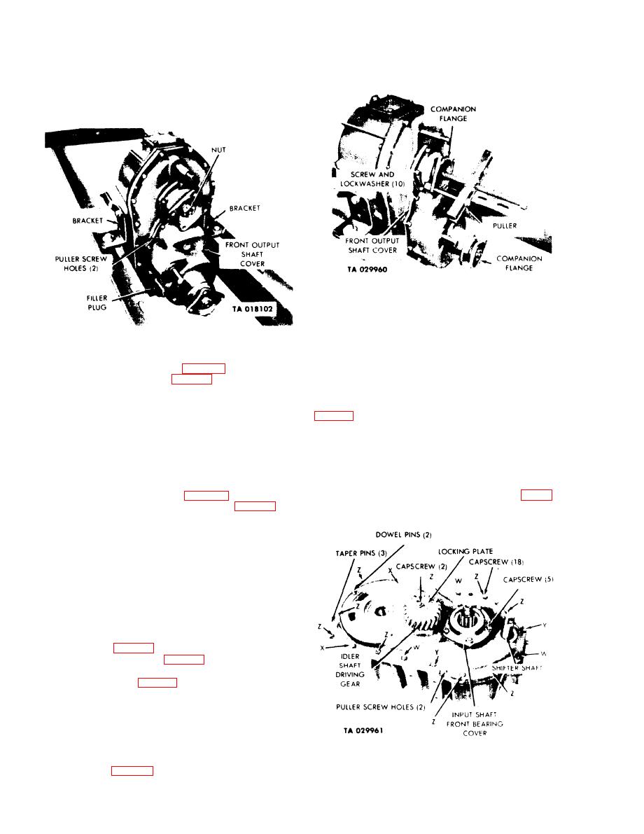
Figure 4-30. Companion Flanges -- Removal.
g. Input Shaft Front Bearing Cover.
NOTE
Figure 4-29. Transfer Mounted on Overhaul Stand,
During assembly, install new gasket and
(1) Using a puller (item 4, table 2-1), remove input
tighten capscrews to 60-77 lb-ft torque.
shaft companion flange. (See fig. 4-30.)
Remove the five capscrews and lockwashers from the
input shaft front bearing cover and cover gasket. (See
NOTE
cover.
Apply a coating of white lead pigment, Fed
Spec TT-W-261C, to front output shaft
h. Idler Shaft Driving Gear.
spline before installing companion flange.
Tighten flange nut.
Bend locking plate tabs away from two
capscrews. Remove the two capscrews securing the
(2) Using a puller (item 4, table 2-1), remove
idler shaft driving gear to the idler shaft. (See fig. 4-
front output shaft companion flange. (See fig. 4-30.)
31.) Remove the idler shaft gear.
e. Front Output Shaft Cover Assembly.
NOTE
During assembly, install new gasket and
tighten capscrews to 45-55 lb-ft torque.
Remove the 10 capscrews and lockwashers
securing the front output shaft cover to the transfer
case cover. (See fig. 4-30.) Install puller screws into
the two puller-screw holes (fig. 4-29) in the flange of
the front output shaft cover. Pull the cover assembly
from the dowel pins (fig. 4-31) on the transfer case
cover. Remove puller screws and discard gasket.
f. Front Output Shaft and Reverse Shift Shaft
Assembly. Position the output shaft cover assembly in
an arbor press with the shafts facing upward and press
the output shaft and reverse shift assembly free from
Figure 4-31. Removal of Transfer Covers.
the cover. (See fig. 4-32.)
4-22
|
|
Privacy Statement - Press Release - Copyright Information. - Contact Us |
