 |
|||
|
|
|||
|
|
|||
| ||||||||||
|
|
 TM 55-4920-416-13
NAVAER 17-15C-539
Section I
PR-1 or PR-2 (8 and 9). PR-3 is in the line at all times which
1-19. The output ports of the vacuum and pressure selector
protects the instruments from pressure overload.
valves connect the vacuum and pressure sections to the
master instruments on the test set panel and to the self-sealing
1-18. VACUUM SECTION. The vacuum section of the test set
quick couplings (19, 20, 21, and 22, figure 1-5) on the rear of
uses the same pump to develop vacuum. Evacuated air from
the test set.
the vacuum section passes through an oil sump (11,
1-20. A group of selector valves (23, 24, 25, 26 and 27,
check-valve (12, figure 1-5). The check valve prevents oil from
entering the instrument lines. Two vacuum control valves (13
panel, provide isolation for the master instruments of the test
and 14, figure 1-5) control the amount of vacuum developed in
set. These valves serve a dual function; namely, to permit
the test set in a manner similar to the pressure controls
case leak tests and/or calibration of the master instruments
described in paragraph 1-17. Setting the vacuum selector
without removing them from the test set.
valve (15, figure 1-5) at the desired test position completes the
circuit to the instrument under test and simultaneously
1-21. The instruments to be tested are connected to tie test
connects the instrument under test and the master instrument
set by means of hoses to the quick couplings described in
to one of three vacuum relief valves (16, 17, and 18, figure 1-5)
which protect the instruments from vacuum overloads.
level as described in paragraphs 1-17 and 1-18 both
instruments, master and aircraft, should show the same
indication.
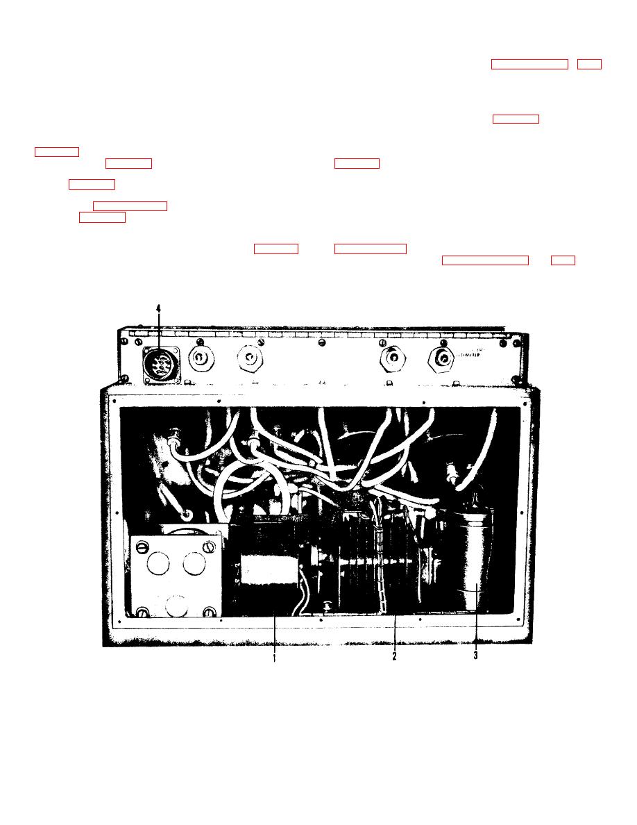
1.
Step-down Transformer
3.
Electrolytic Filter Capacitor
2.
Selenium Rectifier
4.
Power Input Connector
Figure 1-3. Electrical System
5
|
|
Privacy Statement - Press Release - Copyright Information. - Contact Us |
