 |
|||
|
|
|||
|
Page Title:
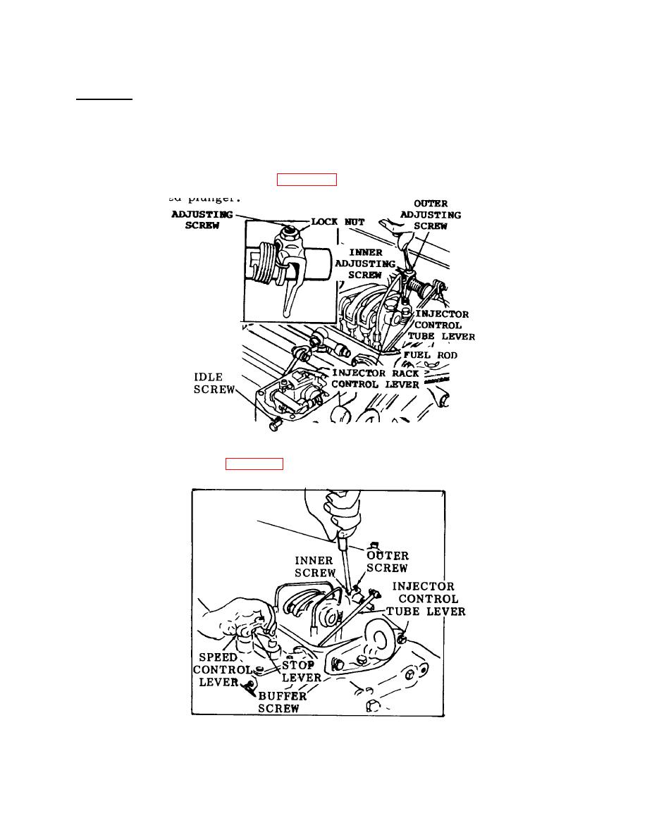
Figure 3-71. Control Rack Lever Adjustment. |
|
||
| ||||||||||
|
|
 TM 55-1930-208-24
3-35. CONTROLS, FUEL INJECTOR - Continued.
h. Adjustment.
NOTE
Always adjust the No. 1 injector rack control lever first.
(1) Disconnect linkage attached to the governor speed control lever.
(2) Turn the idle speed adjusting screw (figure 3-71) until 1/2 inch of the threads project from the locknut,
when the nut is against the high speed plunger.
Figure 3-71. Control Rack Lever Adjustment.
(3) Back out the buffer screw (figure 3-72) approximately 5/8 inch.
Figure 3-72. Positioning No. 1 Injector Rack Control Lever.
3-126
|
|
Privacy Statement - Press Release - Copyright Information. - Contact Us |
