 |
|||
|
|
|||
|
Page Title:
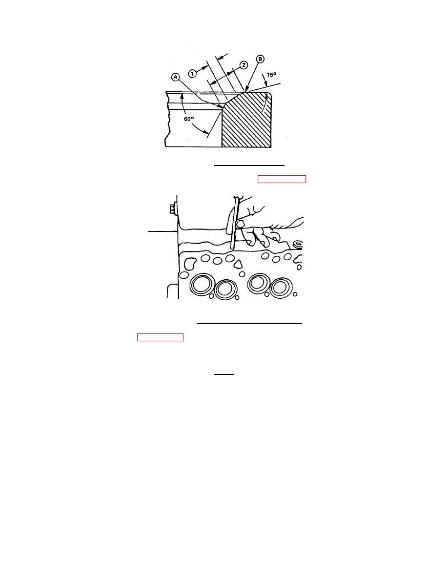
FIGURE 4-23. Grinding Valve Seats. |
|
||
| ||||||||||
|
|
 TM 55-1905-223-24-4
FIGURE 4-23. Grinding Valve Seats.
(12) Mark the cylinder head to identify the re-ground valve seats (FIGURE 4-24).
2404 A
FIGURE 4-24. Marking Re-ground Valve Seats.
f.
Inspect valve springs (3, FIGURE 4-7).
(1) Measure each valve spring.
Limits
Approximate Free Length: 2.190 inch (55.63 mm)
Maximum Inclination: 0.039 inch (1.0 mm)
(2) Using valve spring compression tester, check Valve Spring Tension. A minimum load of 65.0-72.2 lb
(289.32 N.) is required to compress the spring to a height of 1.94 inches (49.25mm).
4-21
|
|
Privacy Statement - Press Release - Copyright Information. - Contact Us |
