 |
|||
|
|
|||
|
Page Title:
Section III. LOCKING DEVICE/ALTERNATE LOCKS |
|
||
| ||||||||||
|
|
 TM 9-8140-381-14&P
(2) Adjust cage cover position until gas spring
(1) At the lower end of the safety bracket
(strut), loosen the nut located between the
slides off mounting studs. Immediately
retighten the lower nut on the stud.
mounting plate and the steel mesh side of
the WSC with a 3/4-inch wrench. A thin
wall (wrench thickness) 1/2-inch open-end
f. Apply a light coating of oil to surface and
wrench should be used to hold the stud
threads of both studs.
between the mounting plate and the lower
safety bracket strut. Do not remove the
g. Install new gas spring
following
reverse
nut.
procedures firom removal.
Section III. LOCKING DEVICE/ALTERNATE LOCKS
2-8.
DESCRIPTION
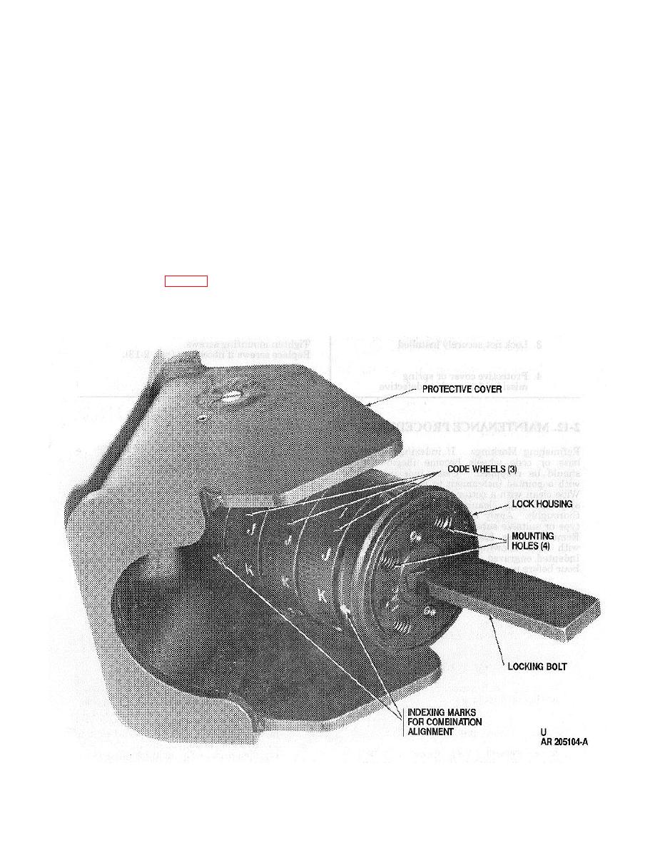
2-8.2. Each code wheel has 11 letters and a diamond
2-8.1. The locking device (fig. 2-3) is a cylindrical lock
symbol. Rotating code wheels to the correct 3-letter
consisting of three code wheels, a rectangular bolt, and
code and pulling knob to the left opens the lock.
a protective cover. The lock is not intended to be a high
security lock.
Figure 2-3. Locking Device with Protective Cover Rotated.
2-5
|
|
Privacy Statement - Press Release - Copyright Information. - Contact Us |
