 |
|||
|
|
|||
|
Page Title:
REMOVING/INSTALLING SPC CIRCUIT CARD ASSEMBLIES (Continued) |
|
||
| ||||||||||
|
|
 TM 9-6920-737-10
REMOVING/INSTALLING SPC CIRCUIT CARD ASSEMBLIES (Continued
)
CAUTION
Use care in removing CCA from logic assembly to prevent catching components on adjacent CCA's.
d.
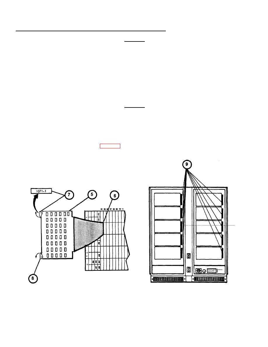
Remove CCA (5) from logic assembly and set aside for possible reinstallation.
6.
Obtain new CCA from Spares and install CCA (5) into logic assembly (6) as follows:
a.
Refer to CCA locater charts (9) attached to the vertical support next to each row of CCA's to verify the CCA
being installed has the correct part number for the intended connector slot.
b.
Verify that identifying number on tab is at top.
CAUTION
Do not use excessive force to install CCA's. CCA's are keyed with four slots at connector end to prevent installation in
wrong location. Excessive force can break the socket. If board cannot be bottomed with firm pressure during installation,
verify part number and location agree with CCA locator charts.
c.
Carefully align CCA in correct guide slot location and push in firmly until bottomed in socket.
7.
Return to Diagnostic Test Procedure (see 3-33, step 19).
3-26
|
|
Privacy Statement - Press Release - Copyright Information. - Contact Us |