 |
|||
|
|
|||
|
Page Title:
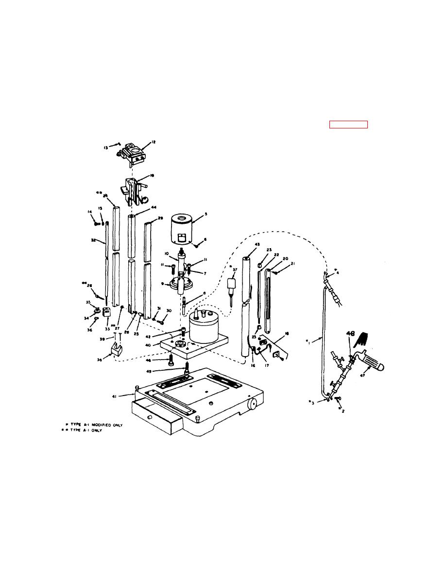
Figure 4-3. Removal of subassemblies. |
|
||
| ||||||||||
|
|
 TM 9-6685-202-14, C1
42.
Screw, cap, socket head HIC 5/16-24 x 1/2
31. Washer, flat HIC No. 4
43.
Rod, thermometer HIC 10-40-01-A
32. Rod, adjusting HIC 10-30-09-A
44.
Rod, scale HIC 10-30-17-B
33. Bracket, adjusting HIC 10-30-08-B
45.
Screw, cap, socket head HIC 1/4-28 x 1 1/4
34. Nut, adjusting HIC 10-30-07-A
46.
Screw, cap, socket head HIC 5/16-24 x 1
35. Washer, spring HIC 10-30-29
47.
Trap, glass 7913095
36.. crew, cap, socket head HIC 4-40 x 3/8
48.
Reducer, flareless tube 7913082
37. Micrometer 7913326
38. Mount, block, gage 7913096
NOTE
39. Screw, cap, socket head MS-16995-30
The key numbers shown below in
40. Cistern base assembly
parenthesis refer to figure 4-3.
41. Platform assembly HIC 10-50-00-A
MI (C) 6685- 202-14-4-3
Figure 4-3. Removal of subassemblies.
NOTE
a. Removal of Subassemblies.
Place the
Steps (1), (18), and (19) below pertain
barometer on a clean working surface and proceed as
follows:
to the type A-1 modified barometer
only.
4-11
|
|
Privacy Statement - Press Release - Copyright Information. - Contact Us |