 |
|||
|
|
|||
|
|
|||
| ||||||||||
|
|
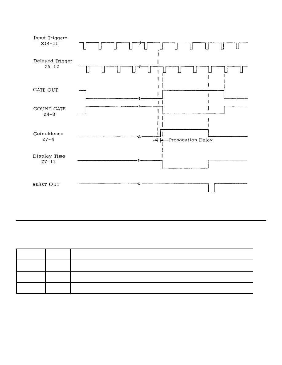
 TIMING DIAGRAM
*100 Hz to 100 KHz internal clock or 1 MHz max. external
Fig. 4-1.
Z8 & Z9 TRUTH TABLE
Q Output
Z8-8
Z9-12
0
0
Reset condition awaiting delayed trigger pulses
1
0
Count gate open, Totalizer and Time Base gates enabled by Z4-9
0
1
Count gate closed, display timer started
1
1
Initiates system reset by enabling Z10-2
Fig. 4-2.
4-19
|
|
Privacy Statement - Press Release - Copyright Information. - Contact Us |