 |
|||
|
|
|||
|
|
|||
| ||||||||||
|
|
 4.2.2
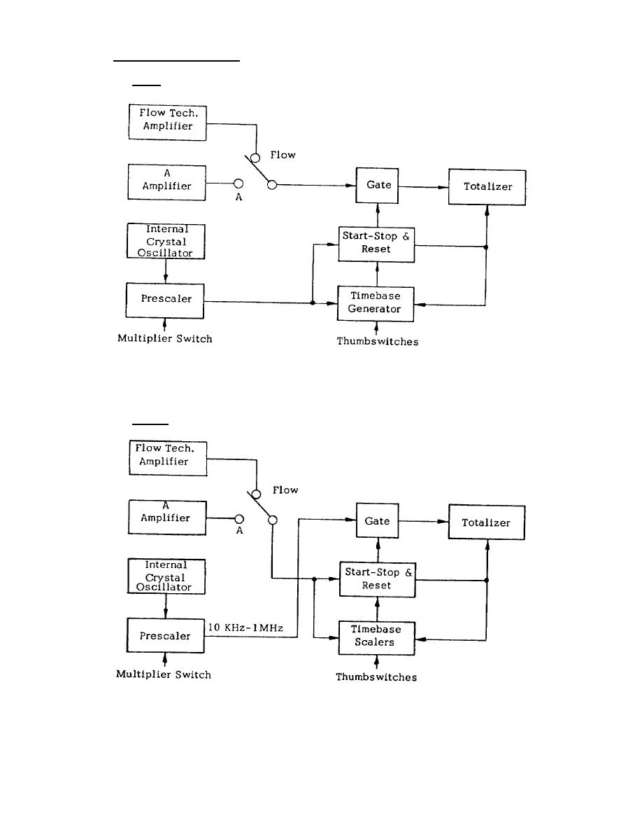
Functional Block Diagrams (Cont'd)
A. RATE
The RATE mode displays the Input signal for the gate time determined by the selection of the
Thumbswitches and Multiplier Switch. The first pulse after reset from the internal oscillator starts the
automatic timing sequence.
B. TIME-A
The TIME-A mode displays the internal crystal oscillator frequency as selected by the Multiplier Switch
for the duration of the gate time determined by the repetitive occurrences of the Input signal. The
Thumbswitches determine the number of repetitive occurrences that are counted. The Input signal also
4-12
|
|
Privacy Statement - Press Release - Copyright Information. - Contact Us |