 |
|||
|
|
|||
|
Page Title:
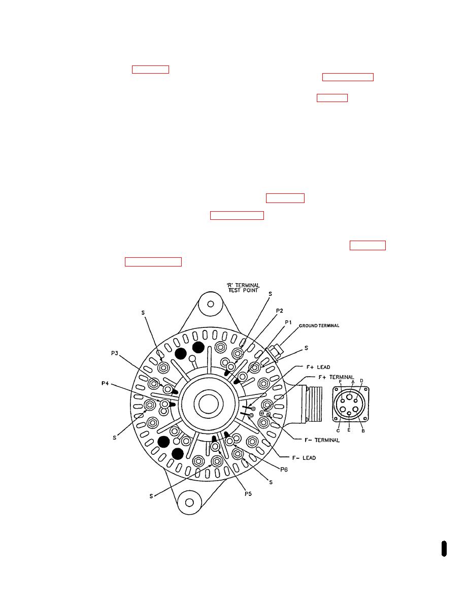
Figure 2-16. Stator Winding Points |
|
||
| ||||||||||
|
|
 TM 9-2920-257-30&P
[2] Reverse phase leads, and observe resistance between pin B or C of the output connector and each
of the six heat sink terminals S (fig. 2-15). All six readings should be very high. If all six readings are not alike, the diode
rectifier assembly is defective. Replace the front housing assembly, in accordance with paragraph 3-4b, steps 1 thru 17.
(6) Stator Tests - Remove all phase leads (P1-P6) from front housing (fig 2-16).
NOTE
A grounded stator is difficult to confirm by static check. Examine stator for burnt
insulation or loose coil.
NOTE
It may be necessary to probe under the sleeves of the phase leads to make
electrical contact.
(a) Open stator winding - Set ohmmeter for X10 scale and make sure ohmmeter is zeroed. Connect
multimeter leads to each successive pair of phase stator windings (fig. 2-16). Ohms should read less than 1 ohm
between each pair of stator phase windings. If ohms reads very high, the stator is open and must be replaced. Replace
or repair stator and shell assembly, in accordance with paragraph 3-4b, steps 1 thru 12.
(b) Shorted stator winding - Set ohmmeter for X1 scale and make sure ohmmeter is zeroed. Connect
multimeter leads to each phase lead and ground terminal located on outside of front housing (fig. 2-16). Ohms should
read very high. If ohms read zero, the stator is grounded and must be replaced. Replace or repair stator and shell
assembly, in accordance with paragraph 3-4b, steps 1 thru 12.
Figure 2-16. Stator Winding Points
Change 1 2-23/(2-24 Blank)
|
|
Privacy Statement - Press Release - Copyright Information. - Contact Us |