 |
|||
|
|
|||
|
Page Title:
Section III. PN N1205 AND N1206 (Niehofl) |
|
||
| ||||||||||
|
|
 TM 9-2920-257-30&P
Section III. PN N1205 AND N1206 (Niehofl)
2-4. ON VEHICLE TEST
a. After the generator has been received by direct support maintenance personnel for preliminary inspection, before
being installed on the engine, or if performance of the generator has been unsatisfactory due to unknown causes, you
must inspect as described in this section.
2-5. TEST SET-UP
a. Refer to vehicle manuals and discharge batteries as follows:
(1) Turn fuel off.
(2) Turn lights and accessories on.
(3) Crank engine for 10-15 seconds to discharge batteries.
(4) Turn lights and accessories off.
(5) Turn fuel on.
b. Determine factory setting of regulator and normal range of regulated voltage (Table 2-2).
Table 2-2. Voltage Regulator Specifications
GENERATOR
SYSTEM
FACTORY
NORMAL
(REGULATOR)
VOLTAGE
SETTING
RANGE
N1205/N1206
24
28.0
26.0 TO 30.0
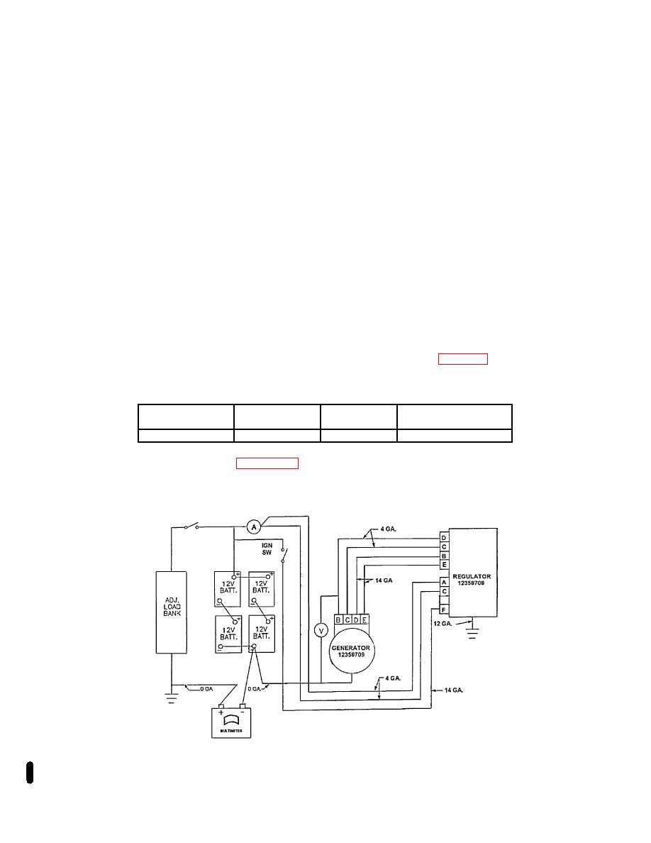
c. Attach multimeter as indicated in Figure 2-13. If an in-line multimeter is used, disconnect battery ground cable
before connecting multimeter. Then reconnect battery ground cable. Multimeter connections must carry rated output of
generator.
Figure 2-13. Charging System Schematic
2-16 Change 1
|
|
Privacy Statement - Press Release - Copyright Information. - Contact Us |