 |
|||
|
|
|||
|
|
|||
| ||||||||||
|
|
 TM 9-2920-252-34&P
3-7. DISASSEMBLY (CONT)
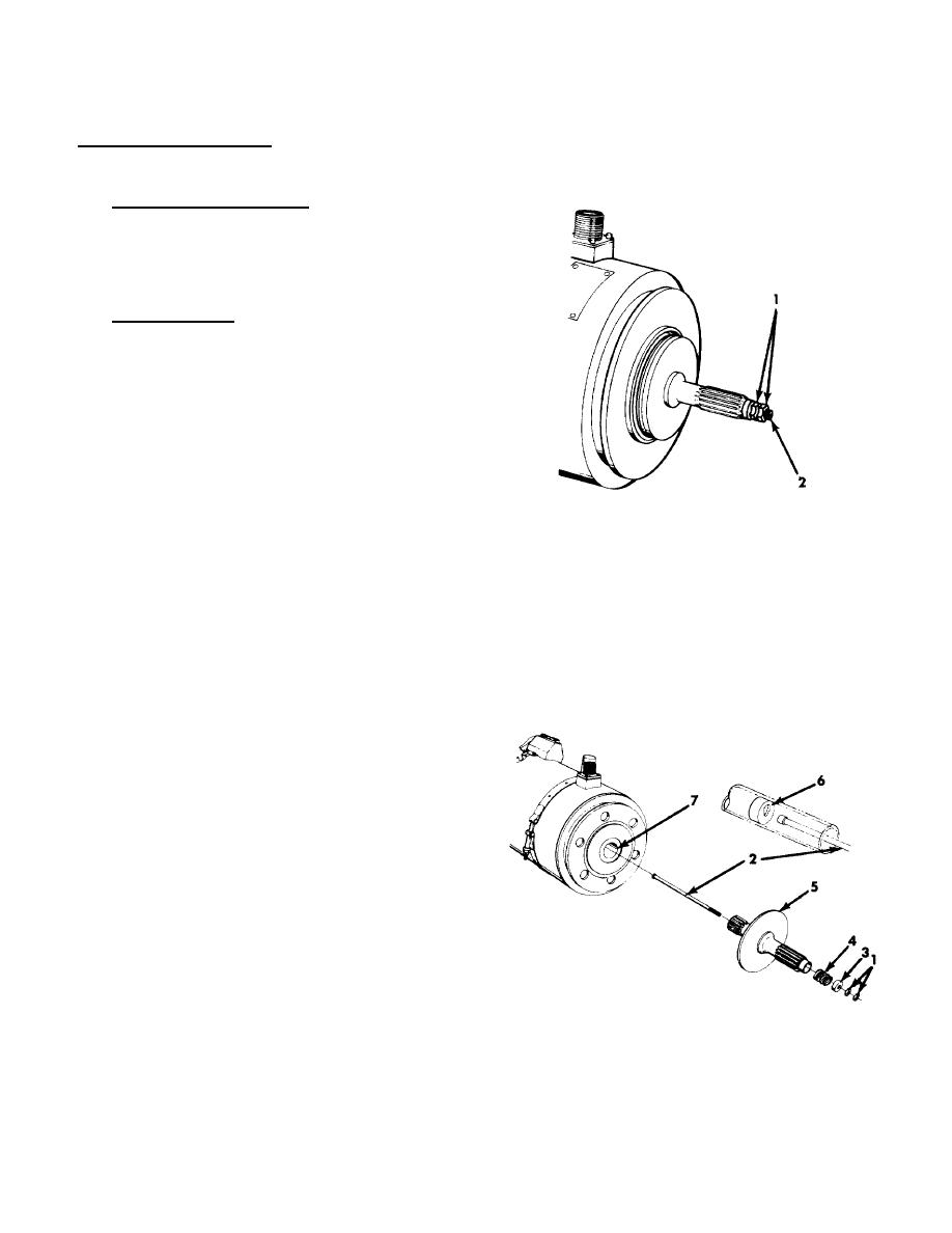
2. DRIVE SHAFT ASSEMBLY.
a. Model 30B95-3-C (Shown). Hold inner nut (1)
with one wrench and loosen outer nut (1) with
second wrench. Hold drive shaft retainer screw
(2) with screwdriver as necessary while removing
nuts (1).
b. Model 30B95-3-B. Hold drive shaft retainer screw
(2) with screwdriver while removing self-locking
nut (1). Discard nut.
c. Remove special washer (3) and spring (4).
d. Inspect spring for cracks and distortion.
e. Load required to compress the spring to a length
of 0.625 inch shall be between 135 to 165 lb-ft
(182 to 223 N ).
m
f. Remove drive shaft assembly (5).
g. head of retainer screw (2) from keyhole (6) and
remove from rotor bore (7).
h. Check drive shaft retainer screw for straightness
and damage to screwdriver slot in threaded end.
Replace if defective.
i. Check drive shaft for smooth inner face.
j. Heresite coating on inner and outer faces of drive
shaft assembly must not be damaged.
k. Check splines for chips, gouges, galling, burs,
and excessive wear. Replace if defective.
l. Check spline wear must not exceed 22.5 degrees
rotation when installed in mating spline.
TA315008
3-6
|
|
Privacy Statement - Press Release - Copyright Information. - Contact Us |