 |
|||
|
|
|||
|
Page Title:
Disassembly of Commutator End Plate Assembly-continued |
|
||
| ||||||||||
|
|
 TM 9- 2920- 232- 34&P / TO 38X14- 2- 32
-
-
-
- -
DISASSEMBLY OF THE STARTER ASSEMBLY - CONTINUED
-
0008 00
NOTE
The 12--brush starters will have pan head screws attaching field leads.
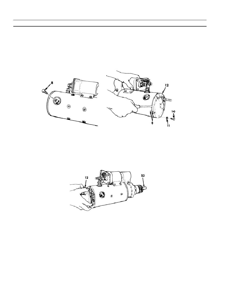
d. Using a 1/4 inch socket tool, remove three hex head screws (8), which attach field leads.
e. Scribe marks (9) on the frame and end plate for realignment at assembly.
f.
Remove six hex head cap screws (10) and lock washers (11). Discard lockwashers.
g. Using a screwdriver, pry end plate (12) away from frame.
h. Push drive end (13) of armature shaft inward as necessary while pulling end plate (12) away from frame.
NOTE
Commutator on armature must be under brushes for tension measurement.
0008 00- 4
-
|
|
Privacy Statement - Press Release - Copyright Information. - Contact Us |